WOLFRAM SYSTEM MODELER
StiffServoMechanismA servo mechanism with a stiff axis |
|
Diagram
Wolfram Language
In[1]:=
SystemModel["IntroductoryExamples.MultiDomain.StiffServoMechanism"]
Out[1]:=
Information
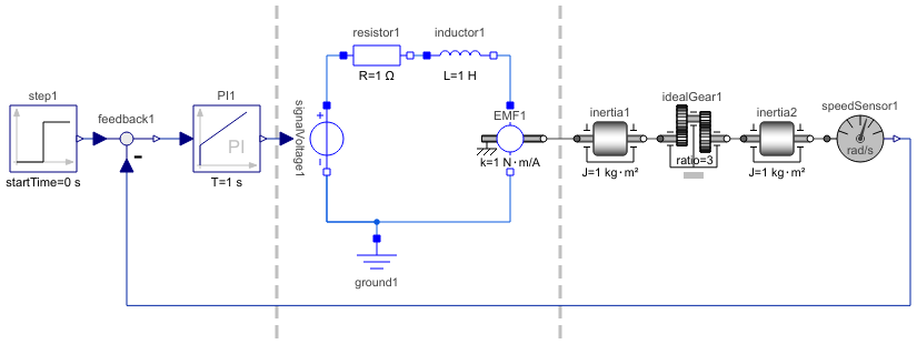
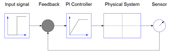
The structure of the control system is shown in the schematic picture below. It consists of an input signal, a sensor, a feedback loop, and a regulator. The physical system consists of the gear and axis system described in DC Motor and Weak Axis. Since the physical system has negative static gain the PI gain also has to be negative.
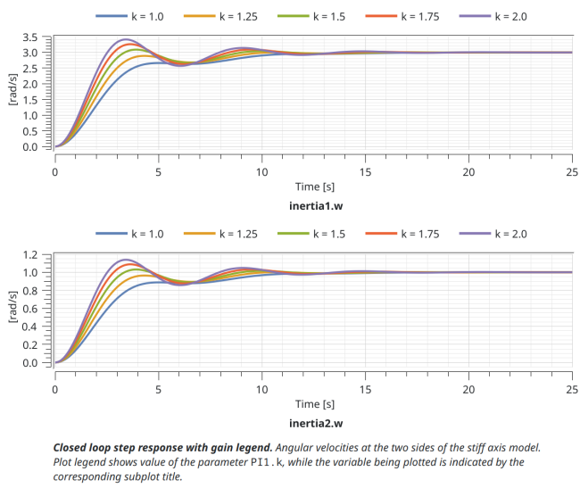
By varying the controller gain k we can study how the system response is affected. In this case we vary the gain from 1 (StiffServoMechanism 1) to 2 (StiffServoMechanism 5) in steps of 0.25. The plot below shows the result:
For a step by step tutorial see Multidomain—A Servo Mechanism.
Components (12)
| idealGear1 |
Type: IdealGear Description: Ideal gear without inertia |
|
|---|---|---|
| inertia1 |
Type: Inertia Description: 1D-rotational component with inertia |
|
| inductor1 |
Type: Inductor Description: Ideal linear electrical inductor |
|
| ground1 |
Type: Ground Description: Ground node |
|
| inertia2 |
Type: Inertia Description: 1D-rotational component with inertia |
|
| feedback1 |
Type: Feedback Description: Output difference between commanded and feedback input |
|
| speedSensor1 |
Type: SpeedSensor Description: Ideal sensor to measure the absolute angular velocity of flange |
|
| signalVoltage1 |
Type: SignalVoltage Description: Generic voltage source using the input signal as source voltage |
|
| PI1 |
Type: PI Description: Proportional-Integral controller |
|
| resistor1 |
Type: Resistor Description: Ideal linear electrical resistor |
|
| EMF1 |
Type: RotationalEMF Description: Electromotoric force (electric/mechanic transformer) |
|
| step1 |
Type: Step Description: Generate step signal of type Real |