WOLFRAM SYSTEM MODELER
LQControlSystemController based on LQ (Linear Quadratic) design |
|
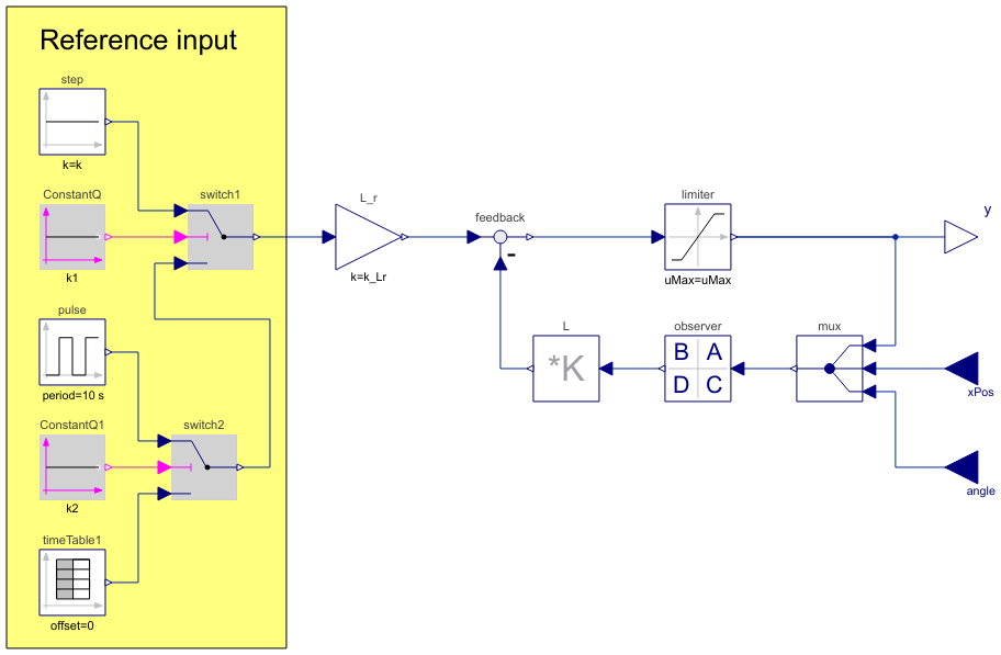
Diagram
Wolfram Language
In[1]:=
SystemModel["IntroductoryExamples.Systems.Components.LQControlSystem"]
Out[1]:=
Information
This is a LQ (Linear Quadratic) design of a controller for an inverted pendulum. It contains a number of different reference inputs in order to change system behavior. The reference input type is changed with the parameter referenceType. The output signal is limited to get a realistic response.
The observer has been implemented in a state space block and the position and angle is measured.
Parameters (9)
| A |
Value: {{-1.80378, 1.0, -0.301845, 0.0}, {-1.67236, -13.7653, -0.753808, 0.0}, {-0.301845, 0.0, -7.83137, 1.0}, {-0.617197, -19.3623, -14.7496, 0.0}} Type: Real[:,:] Description: Observer A matrix |
|---|---|
| B |
Value: {{0.0, 1.80378, 0.301845}, {2.69088, 1.67236, 2.29112}, {0.0, 0.301845, 7.83137}, {3.785, 0.617197, 30.7107}} Type: Real[:,:] Description: Observer B matrix |
| C |
Value: {{1, 0, 0, 0}, {0, 1, 0, 0}, {0, 0, 1, 0}, {0, 0, 0, 1}} Type: Real[:,:] Description: Observer C matrix |
| D |
Value: {{0, 0, 0}, {0, 0, 0}, {0, 0, 0}, {0, 0, 0}} Type: Real[:,:] Description: Observer D matrix |
| K_L |
Value: {{-14.1421, -23.685, 114.738, 21.4806}} Type: Real[:,:] Description: L matrix such that eigenvalues for A-B*L is inside stability region |
| k_Lr |
Value: -14.1421 Type: Real Description: Static gain in order to make system gain equal to one |
| uMax |
Value: 10 Type: Real Description: Maximum output value |
| table |
Value: [0, 0; 1, 1; 5, 1; 5.5, 2; 6, 0; 6.5, 2; 7, 1; 4.5, 1; 10, 1; 10.5, 0; 11, 2; 11.5, 0; 12, 1; 20, 1] Type: Real[:,2] Description: Table matrix (time = first column). Only if inputType=3 |
| referenceType |
Value: 2 Type: Integer Description: Type of reference signal: 1=step, 2=pulse, 3=time table |
Connectors (3)
| angle |
Type: RealInput Description: 'input Real' as connector |
|
|---|---|---|
| xPos |
Type: RealInput Description: 'input Real' as connector |
|
| y |
Type: RealOutput Description: 'output Real' as connector |
Components (13)
| step |
Type: Constant Description: Generate constant signal of type Real |
|
|---|---|---|
| observer |
Type: StateSpace Description: Linear state space system |
|
| L |
Type: MatrixGain Description: Output the product of a gain matrix with the input signal vector |
|
| feedback |
Type: Feedback Description: Output difference between commanded and feedback input |
|
| L_r |
Type: Gain Description: Output the product of a gain value with the input signal |
|
| mux |
Type: Multiplex3 Description: Multiplexer block for three input connectors |
|
| pulse |
Type: Pulse Description: Generate pulse signal of type Real |
|
| switch1 |
Type: Switch Description: Switch between two Real signals |
|
| ConstantQ |
Type: BooleanConstant Description: Generate constant signal of type Boolean |
|
| limiter |
Type: Limiter Description: Limit the range of a signal |
|
| switch2 |
Type: Switch Description: Switch between two Real signals |
|
| ConstantQ1 |
Type: BooleanConstant Description: Generate constant signal of type Boolean |
|
| timeTable1 |
Type: TimeTable Description: Generate a (possibly discontinuous) signal by linear interpolation in a table |
Used in Examples (1)
|
IntroductoryExamples.Systems A controlled inverted pendulum system |