WOLFRAM SYSTEM MODELER
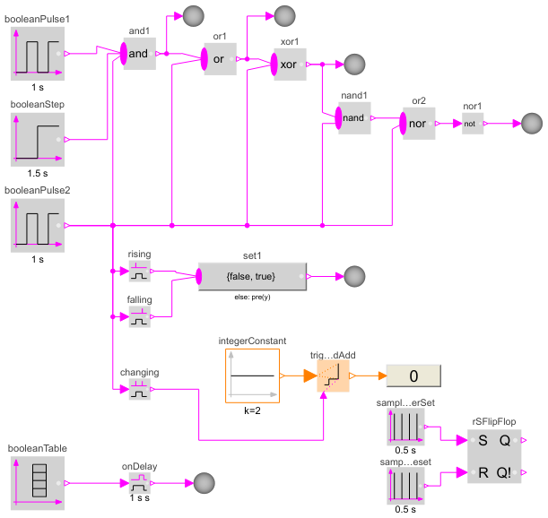
BooleanNetwork1Demonstrates the usage of blocks from Modelica.Blocks.MathBoolean |
|
Diagram
Wolfram Language
In[1]:=
SystemModel["Modelica.Blocks.Examples.BooleanNetwork1"]
Out[1]:=

Information
This information is part of the Modelica Standard Library maintained by the Modelica Association.
This example demonstrates a network of Boolean blocks from package Modelica.Blocks.MathBoolean. Note, that
- at the right side of the model, several MathBoolean.ShowValue blocks are present, that visualize the actual value of the respective Boolean signal in a diagram animation ("green" means "true").
- the Boolean values of the input and output signals are visualized in the diagram animation, by the small "circles" close to the connectors. If a "circle" is "white", the signal is false. If a "circle" is "green", the signal is true.
Components (27)
| showValue |
Type: BooleanValue Description: Show Boolean value from numberPort or from number input field in diagram layer dynamically |
|
|---|---|---|
| and1 |
Type: And Description: Logical 'and': y = u[1] and u[2] and ... and u[nu] |
|
| booleanPulse1 |
Type: BooleanPulse Description: Generate pulse signal of type Boolean |
|
| booleanPulse2 |
Type: BooleanPulse Description: Generate pulse signal of type Boolean |
|
| booleanStep |
Type: BooleanStep Description: Generate step signal of type Boolean |
|
| or1 |
Type: Or Description: Logical 'or': y = u[1] or u[2] or ... or u[nu] |
|
| xor1 |
Type: Xor Description: Logical 'xor': y = oneTrue(u) (y is true, if exactly one element of u is true, otherwise it is false) |
|
| showValue2 |
Type: BooleanValue Description: Show Boolean value from numberPort or from number input field in diagram layer dynamically |
|
| showValue3 |
Type: BooleanValue Description: Show Boolean value from numberPort or from number input field in diagram layer dynamically |
|
| nand1 |
Type: Nand Description: Logical 'nand': y = not ( u[1] and u[2] and ... and u[nu] ) |
|
| or2 |
Type: Nor Description: Logical 'nor': y = not ( u[1] or u[2] or ... or u[nu] ) |
|
| showValue4 |
Type: BooleanValue Description: Show Boolean value from numberPort or from number input field in diagram layer dynamically |
|
| nor1 |
Type: Not Description: Logical 'not': y = not u |
|
| onDelay |
Type: OnDelay Description: Delay a rising edge of the input, but do not delay a falling edge. |
|
| rising |
Type: RisingEdge Description: Output y is true, if the input u has a rising edge, otherwise it is false (y = edge(u)) |
|
| set1 |
Type: MultiSwitch Description: Set Boolean expression that is associated with the first active input signal |
|
| falling |
Type: FallingEdge Description: Output y is true, if the input u has a falling edge, otherwise it is false (y = edge(not u)) |
|
| booleanTable |
Type: BooleanTable Description: Generate a Boolean output signal based on a vector of time instants |
|
| changing |
Type: ChangingEdge Description: Output y is true, if the input u has either a rising or a falling edge and otherwise it is false (y=change(u)) |
|
| triggeredAdd |
Type: TriggeredAdd Description: Add input to previous value of output, if rising edge of trigger port |
|
| integerConstant |
Type: IntegerConstant Description: Generate constant signal of type Integer |
|
| showValue1 |
Type: IntegerValue Description: Show Integer value from numberPort or from number input field in diagram layer dynamically |
|
| showValue5 |
Type: BooleanValue Description: Show Boolean value from numberPort or from number input field in diagram layer dynamically |
|
| showValue6 |
Type: BooleanValue Description: Show Boolean value from numberPort or from number input field in diagram layer dynamically |
|
| rSFlipFlop |
Type: RSFlipFlop Description: A basic RS Flip Flop |
|
| sampleTriggerSet |
Type: SampleTrigger Description: Generate sample trigger signal |
|
| sampleTriggerReset |
Type: SampleTrigger Description: Generate sample trigger signal |