WOLFRAM SYSTEM MODELER
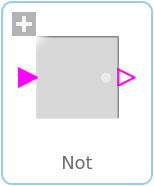
NotLogical 'not': y = not u |
|
Wolfram Language
In[1]:=
SystemModel["Modelica.Blocks.MathBoolean.Not"]
Out[1]:=
Information
This information is part of the Modelica Standard Library maintained by the Modelica Association.
The output is false if at least one input is true, otherwise the output is true.
The input connector is a vector of Boolean input signals. When a connection line is drawn, the dimension of the input vector is enlarged by one and the connection is automatically connected to this new free index (thanks to the connectorSizing annotation).
The usage is demonstrated, e.g., in example Modelica.Blocks.Examples.BooleanNetwork1.
Connectors (2)
| u |
Type: BooleanInput Description: Boolean input signal |
|
|---|---|---|
| y |
Type: BooleanOutput Description: Boolean output signal |
Used in Examples (1)
|
Modelica.Blocks.Examples Demonstrates the usage of blocks from Modelica.Blocks.MathBoolean |
Used in Components (1)
|
Modelica.Clocked.BooleanSignals.NonPeriodic Block to translate clock signals to continuous Boolean events (each time the input clock ticks a rising Boolean output edge is produced). |