WOLFRAM SYSTEM MODELER
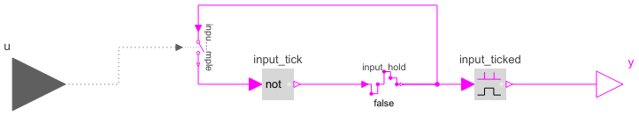
ClockToBooleanBlock to translate clock signals to continuous Boolean events (each time the input clock ticks a rising Boolean output edge is produced). |
|
Diagram
Wolfram Language
In[1]:=
SystemModel["Modelica.Clocked.BooleanSignals.NonPeriodic.ClockToBoolean"]
Out[1]:=
Connectors (2)
| u |
Type: ClockInput Description: Connector of clock input signal. |
|
|---|---|---|
| y |
Type: BooleanOutput Description: Connector of continuous Boolean output signal. |
Components (4)
| input_sample |
Type: SampleClocked Description: Sample the continuous-time, Boolean input signal and provide it as clocked output signal. The clock is provided as input signal |
|
|---|---|---|
| input_tick |
Type: Not Description: Logical 'not': y = not u |
|
| input_hold |
Type: Hold Description: Hold the clocked, Boolean input signal and provide it as continuous-time output signal (zero order hold) |
|
| input_ticked |
Type: ChangingEdge Description: Output y is true, if the input u has either a rising or a falling edge and otherwise it is false (y=change(u)) |
Used in Components (1)
|
Modelica.Clocked.ClockSignals.Clocks.Logical Logical clock combining arbitrary many input clock signals according to a replaceable logical combinator |