WOLFRAM SYSTEM MODELER
LogicalLibrary of components with Boolean input and output signals |
|
Package Contents
|
Logical 'and': y = u1 and u2 |
|
|
Logical 'or': y = u1 or u2 |
|
|
Logical 'xor': y = u1 xor u2 |
|
|
Logical 'nor': y = not (u1 or u2) |
|
|
Logical 'nand': y = not (u1 and u2) |
|
|
Logical 'not': y = not u |
|
|
Breaks algebraic loops by an infinitesimal small time delay (y = pre(u): event iteration continues until u = pre(u)) |
|
|
Output y is true, if the input u has a rising edge (y = edge(u)) |
|
|
Output y is true, if the input u has a falling edge (y = edge(not u)) |
|
|
Output y is true, if the input u has a rising or falling edge (y = change(u)) |
|
|
Output y is true, if input u is greater than threshold |
|
|
Output y is true, if input u is greater or equal than threshold |
|
|
Output y is true, if input u is less than threshold |
|
|
Output y is true, if input u is less or equal than threshold |
|
|
Output y is true, if input u1 is greater than input u2 |
|
|
Output y is true, if input u1 is greater or equal than input u2 |
|
|
Output y is true, if input u1 is less than input u2 |
|
|
Output y is true, if input u1 is less or equal than input u2 |
|
|
Trigger zero crossing of input u |
|
|
Logical Switch |
|
|
Switch between two Real signals |
|
|
Transform Real to Boolean signal with Hysteresis |
|
|
On-off controller |
|
|
Triggered trapezoid generator |
|
|
Timer measuring the time from the time instant where the Boolean input became true |
|
|
Delay boolean signal |
|
|
A basic RS Flip Flop |
|
|
Assert that input u is true |
|
|
Terminate simulation if condition is fulfilled |
Information
This information is part of the Modelica Standard Library maintained by the Modelica Association.
This package provides blocks with Boolean input and output signals to describe logical networks. A typical example for a logical network built with package Logical is shown in the next figure:
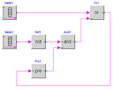
The actual value of Boolean input and/or output signals is displayed in the respective block icon as "circle", where "white" color means value false and "green" color means value true. These values are visualized in a diagram animation.
Wolfram Language
In[1]:=
SystemModel["Modelica.Blocks.Logical"]
Out[1]:=