WOLFRAM SYSTEM MODELER
EngineInternal combustion engine. |
|
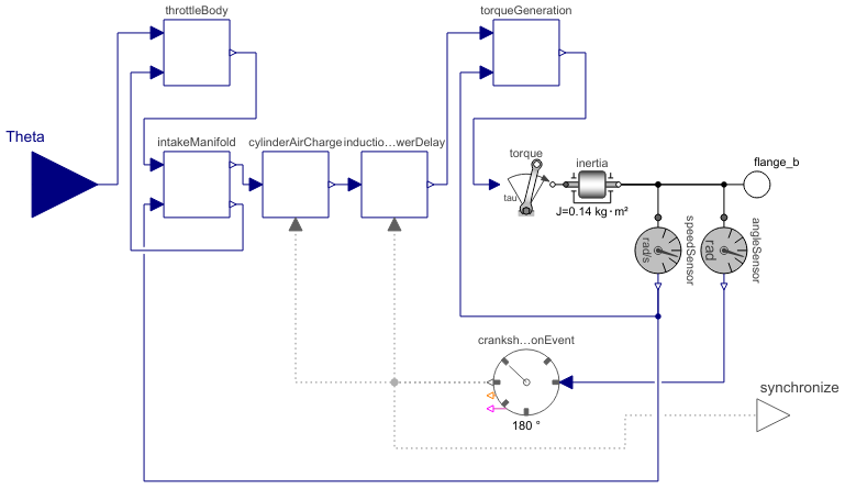
Diagram
Wolfram Language
In[1]:=
SystemModel["Modelica.Clocked.Examples.Systems.Utilities.ComponentsThrottleControl.Engine"]
Out[1]:=
Connectors (3)
| Theta |
Type: RealInput Description: Throttle angle (deg) |
|
|---|---|---|
| flange_b |
Type: Flange_b Description: One-dimensional rotational flange of a shaft (non-filled circle icon) |
|
| synchronize |
Type: ClockOutput Description: 'output Clock' as connector |
Components (10)
| throttleBody |
Type: ThrottleBody Description: Basic throttle body equations |
|
|---|---|---|
| intakeManifold |
Type: IntakeManifold Description: Dynamics of the intake manifold |
|
| torqueGeneration |
Type: TorqueGeneration Description: Torque generation |
|
| crankshaftPositionEvent |
Type: FixedRotationalClock Description: Event clock generating a clock tick each time an observed input angle changed for a certain, constant rotational-interval |
|
| inductionToPowerDelay |
Type: InductionToPowerDelay Description: Accounts for the induction-to-power stroke lag. |
|
| cylinderAirCharge |
Type: CylinderAirCharge Description: Integrates the air mass flow into a cylinder. After the charge for one cylinder is complete, resets the mass to 0. |
|
| torque |
Type: Torque Description: Input signal acting as external torque on a flange |
|
| inertia |
Type: Inertia Description: 1D-rotational component with inertia |
|
| speedSensor |
Type: SpeedSensor Description: Ideal sensor to measure the absolute angular velocity of flange |
|
| angleSensor |
Type: AngleSensor Description: Ideal sensor to measure the absolute angle of flange |
Used in Examples (1)
|
Modelica.Clocked.Examples.Systems Closed-loop throttle control synchronized to the crankshaft angle of an internal combustion engine |