WOLFRAM SYSTEM MODELER
ControlCircuitControl circuit |
|
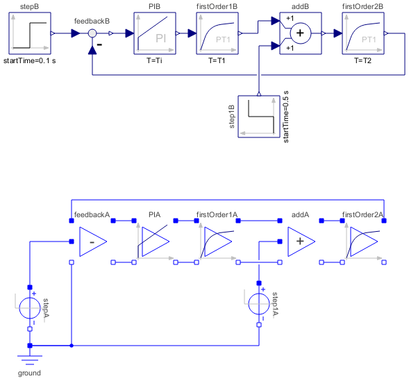
Diagram
Wolfram Language
In[1]:=
SystemModel["Modelica.Electrical.Analog.Examples.OpAmps.ControlCircuit"]
Out[1]:=
Information
This information is part of the Modelica Standard Library maintained by the Modelica Association.
This is an analog control circuit with operational amplifiers.
Compare the analog solution with the block circuit, e.g. firstOrder2B.y and firstOrder2A.v2.
Parameters (4)
Components (15)
| ground |
Type: Ground Description: Ground node |
|
|---|---|---|
| stepA |
Type: StepVoltage Description: Step voltage source |
|
| feedbackA |
Type: Feedback Description: Subtracting operational amplifier circuit |
|
| PIA |
Type: PI Description: PI controller operational amplifier circuit |
|
| firstOrder1A |
Type: FirstOrder Description: Lowpass filter operational amplifier circuit |
|
| addA |
Type: Add Description: Adding operational amplifier circuit |
|
| step1A |
Type: StepVoltage Description: Step voltage source |
|
| firstOrder2A |
Type: FirstOrder Description: Lowpass filter operational amplifier circuit |
|
| stepB |
Type: Step Description: Generate step signal of type Real |
|
| feedbackB |
Type: Feedback Description: Output difference between commanded and feedback input |
|
| PIB |
Type: PI Description: Proportional-Integral controller |
|
| firstOrder1B |
Type: FirstOrder Description: First order transfer function block (= 1 pole) |
|
| addB |
Type: Add Description: Output the sum of the two inputs |
|
| step1B |
Type: Step Description: Generate step signal of type Real |
|
| firstOrder2B |
Type: FirstOrder Description: First order transfer function block (= 1 pole) |