WOLFRAM SYSTEM MODELER
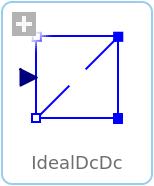
IdealDcDcIdeal DC-DC inverter |
|
Diagram
Wolfram Language

SystemModel["Modelica.Electrical.Machines.Examples.ControlledDCDrives.Utilities.IdealDcDc"]

Information
This information is part of the Modelica Standard Library maintained by the Modelica Association.
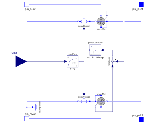
This is a model of an ideal DC-DC inverter based on a power balance achieved by an integral controller.
Parameters (2)
Connectors (5)
| pin_nBat |
Type: NegativePin Description: Negative pin of an electrical component |
|
|---|---|---|
| pin_pBat |
Type: PositivePin Description: Positive pin of an electrical component |
|
| pin_nMot |
Type: NegativePin Description: Negative pin of an electrical component |
|
| pin_pMot |
Type: PositivePin Description: Positive pin of an electrical component |
|
| vRef |
Type: RealInput Description: 'input Real' as connector |
Components (8)
| signalVoltage |
Type: SignalVoltage Description: Generic voltage source using the input signal as source voltage |
|
|---|---|---|
| signalCurrent |
Type: SignalCurrent Description: Generic current source using the input signal as source current |
|
| powerBat |
Type: PowerSensor Description: Sensor to measure the power |
|
| powerMot |
Type: PowerSensor Description: Sensor to measure the power |
|
| deadTime |
Type: FirstOrder Description: First order transfer function block (= 1 pole) |
|
| feedback |
Type: Feedback Description: Output difference between commanded and feedback input |
|
| powerController |
Type: Integrator Description: Output the integral of the input signal with optional reset |
|
| groundMotor |
Type: Ground Description: Ground node |
Used in Components (1)
|
Modelica.Electrical.Machines.Examples.ControlledDCDrives.Utilities DC-DC inverter |

