WOLFRAM SYSTEM MODELER
DCPM_DriveTest example: drive with 2 permanent magnet DC machines |
|
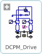
Diagram
Wolfram Language
In[1]:=
SystemModel["Modelica.Electrical.Machines.Examples.DCMachines.DCPM_Drive"]
Out[1]:=
Information
This information is part of the Modelica Standard Library maintained by the Modelica Association.
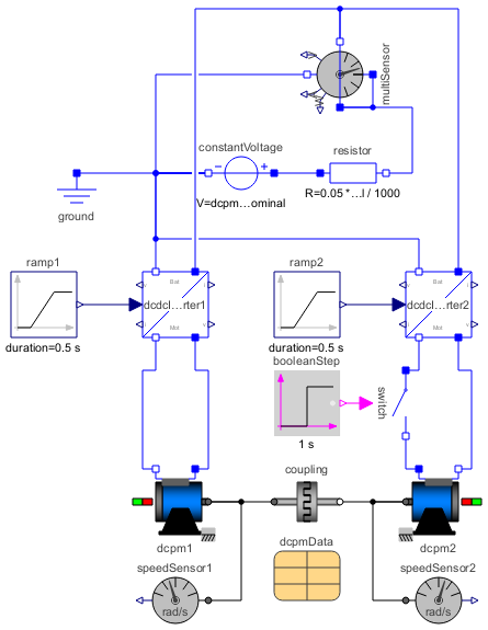
This example demonstrates how to use a coupling
to implement a drive consisting if two permanent magnet DC machines.
Note that dcpm1 is turning in the positive direction, whereas dcpm2 is turning in the opposite direction.
This is evident by comparing speedSensor1.w and speedSensor2.w.
Therefore, the armature of dcpm2 is connected reversed to the source.
Machine dcpm1 starts the drive with a voltage ramp up to half of no-load speed, the armature of dcpm2 is not connected.
Since the induced voltage of dcpm2 is the same as that of dcdcInverter2, the switch is closed without any transient.
After that, the armature voltage of dcpm2 is slightly increased, causing dcpm2 to drive as motor and dcpm1 to brake as generator.
Therefore, the speed coupling.w increases.
Note that in stationary operation the battery only delivers the losses of both machines, since power is exchanged directly between both machines.
Only during short time spans with transient operation power is delivered back to the battery,
which is the case after accelerating the whole drive when angular velocity settles.
An additional energy storage between the battery and the inverters (like a large capacitor or a super capacitor) would help to avoid such situations
and to smooth possible current spikes.
Parameters (1)
| dcpmData |
Type: DcPermanentMagnetData Description: DC machine data |
|---|
Components (16)
| dcpmData |
Type: DcPermanentMagnetData Description: DC machine data |
|
|---|---|---|
| dcpm1 |
Type: DC_PermanentMagnet Description: Permanent magnet DC machine |
|
| dcpm2 |
Type: DC_PermanentMagnet Description: Permanent magnet DC machine |
|
| coupling |
Type: Coupling Description: Ideal rotational coupling |
|
| dcdcInverter1 |
Type: DcdcInverter Description: DC-DC inverter |
|
| dcdcInverter2 |
Type: DcdcInverter Description: DC-DC inverter |
|
| ramp1 |
Type: Ramp Description: Generate ramp signal |
|
| ramp2 |
Type: Ramp Description: Generate ramp signal |
|
| switch |
Type: IdealClosingSwitch Description: Ideal electrical closer |
|
| booleanStep |
Type: BooleanStep Description: Generate step signal of type Boolean |
|
| multiSensor |
Type: MultiSensor Description: Sensor to measure current, voltage and power |
|
| constantVoltage |
Type: ConstantVoltage Description: Source for constant voltage |
|
| resistor |
Type: Resistor Description: Ideal linear electrical resistor |
|
| ground |
Type: Ground Description: Ground node |
|
| speedSensor1 |
Type: SpeedSensor Description: Ideal sensor to measure the absolute angular velocity of flange |
|
| speedSensor2 |
Type: SpeedSensor Description: Ideal sensor to measure the absolute angular velocity of flange |