WOLFRAM SYSTEM MODELER
CouplingIdeal rotational coupling |
|
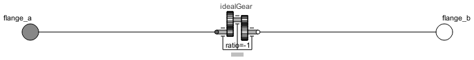
Diagram
Wolfram Language
In[1]:=
SystemModel["Modelica.Electrical.Machines.Utilities.Coupling"]
Out[1]:=
Information
This information is part of the Modelica Standard Library maintained by the Modelica Association.
This is a model of an ideal stiff coupling:
One device connected to the coupling is turning clockwise (looking at the shaft end),
the other device connected to the coupling is turning counter-clockwise (looking at the shaft end).
The torque at flange_b has the same magnitude as the torque at flange_a but opposite sign.
This is achieved by using an
ideal gear with ratio = -1.
Variable w represents the angular velocity of flange_a
and tau represents the torque transferred from flange_a to flange_b.
This behaviour is essential when coupling electric machines. The usage is demonstrated in the example Modelica.Electrical.Machines.Examples.DCMachines.DCPM_Drive.
Connectors (2)
Components (1)
| idealGear |
Type: IdealGear Description: Ideal gear without inertia |
|---|
Used in Examples (1)
|
Modelica.Electrical.Machines.Examples.DCMachines Test example: drive with 2 permanent magnet DC machines |