WOLFRAM SYSTEM MODELER
ChopperBuckBoost_DutyCycle |
|
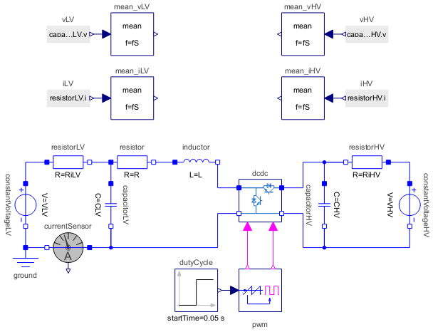
Diagram
Wolfram Language
In[1]:=
SystemModel["Modelica.Electrical.PowerConverters.Examples.DCDC.ChopperBuckBoost.ChopperBuckBoost_DutyCycle"]
Out[1]:=
Information
This information is part of the Modelica Standard Library maintained by the Modelica Association.
This examples demonstrates bidirectional coupling of two batteries with different voltages as used in automotive.
For idleDutyCycle = 1 - (VLV/VHV), no current is exchanged.
Starting with dutyCycle < idleDutyCycle, the high voltage battery feeds the low voltage battery.
Changing the dutyCycle > idleDutyCycle, the low voltage battery feeds the high voltage battery.
The capacitors are precharged to the battery voltages, but the inductor leads zero current. The current sensor may be used to implement current control.
Control
For hints implementing control, see: Stefan Norbert Matlok, Digitale Regelung bidirektionaler Gleichspannungswandler (German, Digital control of bidirectional DC/DC converters), PhD thesis University Erlangen-Nuremberg 2020.
Parameters (10)
| VLV |
Value: 12 Type: Voltage (V) Description: LV voltage |
|---|---|
| RiLV |
Value: 0.01 Type: Resistance (Ω) Description: LV inner resistance |
| VHV |
Value: 24 Type: Voltage (V) Description: HV voltage |
| RiHV |
Value: 0.01 Type: Resistance (Ω) Description: HV inner resistance |
| CLV |
Value: 500e-6 Type: Capacitance (F) Description: Low voltage capacitance |
| CHV |
Value: 250e-6 Type: Capacitance (F) Description: High voltage capacitance |
| L |
Value: 10e-6 Type: Inductance (H) Description: Inductance |
| R |
Value: 1e-3 Type: Resistance (Ω) Description: Resistance of inductor |
| fS |
Value: 40e3 Type: Frequency (Hz) Description: Switching frequency |
| idleDutyCycle |
Value: 1 - VLV / VHV Type: Real Description: Duty cycle for idle operation |
Components (21)
| dcdc |
Type: ChopperBuckBoost Description: Bidirectional chopper |
|
|---|---|---|
| constantVoltageLV |
Type: ConstantVoltage Description: Source for constant voltage |
|
| resistorLV |
Type: Resistor Description: Ideal linear electrical resistor |
|
| ground |
Type: Ground Description: Ground node |
|
| capacitorLV |
Type: Capacitor Description: Ideal linear electrical capacitor |
|
| resistor |
Type: Resistor Description: Ideal linear electrical resistor |
|
| inductor |
Type: Inductor Description: Ideal linear electrical inductor |
|
| capacitorHV |
Type: Capacitor Description: Ideal linear electrical capacitor |
|
| constantVoltageHV |
Type: ConstantVoltage Description: Source for constant voltage |
|
| resistorHV |
Type: Resistor Description: Ideal linear electrical resistor |
|
| vLV |
Type: RealExpression Description: Set output signal to a time varying Real expression |
|
| iLV |
Type: RealExpression Description: Set output signal to a time varying Real expression |
|
| vHV |
Type: RealExpression Description: Set output signal to a time varying Real expression |
|
| iHV |
Type: RealExpression Description: Set output signal to a time varying Real expression |
|
| mean_vLV |
Type: Mean Description: Calculate mean over period 1/f |
|
| mean_iLV |
Type: Mean Description: Calculate mean over period 1/f |
|
| mean_vHV |
Type: Mean Description: Calculate mean over period 1/f |
|
| mean_iHV |
Type: Mean Description: Calculate mean over period 1/f |
|
| pwm |
Type: SignalPWM Description: Generates a pulse width modulated (PWM) boolean fire signal |
|
| currentSensor |
Type: CurrentSensor Description: Sensor to measure the current in a branch |
|
| dutyCycle |
Type: Step Description: Generate step signal of type Real |