WOLFRAM SYSTEM MODELER
FirstExampleA first example |
|
Wolfram Language
In[1]:=
SystemModel["Modelica.Mechanics.MultiBody.UsersGuide.Tutorial.FirstExample"]
Out[1]:=
Information
This information is part of the Modelica Standard Library maintained by the Modelica Association.
As a first example it shall be demonstrated how to build up, simulate and animate a simple pendulum.
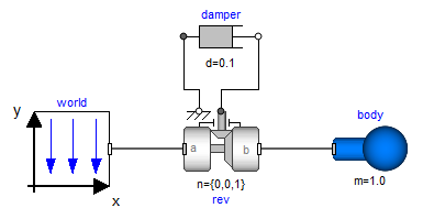
A simple pendulum consisting of a body and a revolute joint with linear damping in the joint, is first build-up as Modelica composition diagram, resulting in:
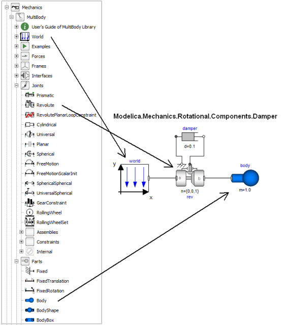
In the following figure the location of the used model components is shown. Drag these components in the diagram layer and connect them according to the figure:
Every model that uses model components from the MultiBody library must have an instance of the Modelica.Mechanics.MultiBody.World model on highest level. The reason is that in the world object the gravity field is defined (uniform gravity or point gravity), as well as the default sizes of animation shapes and this information is reported to all used components. If the World object is missing, a warning message is printed and an instance of the World object with default settings is automatically utilized (this feature is defined with annotations).
In a second step the parameters of the dragged components need to be defined. Some parameters are vectors that have to be defined with respect to a local coordinate system of the corresponding component. The easiest way to perform this is to define a reference configuration of your multi-body model: In this configuration, the relative coordinates of all joints are zero. This means that all coordinate systems on all components are parallel to each other. Therefore, this just means that all vectors are resolved in the world frame in this configuration.
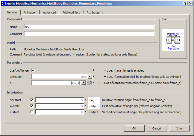
The reference configuration for the simple pendulum shall be defined in the following way: The y-axis of the world frame is directed upwards, i.e., the opposite direction of the gravity acceleration. The x-axis of the world frame is orthogonal to it. The revolute joint is placed in the origin of the world frame. The rotation axis of the revolute joint is directed along the z-axis of the world frame. The body is placed on the x-axis of the world frame (i.e., the rotation angle of the revolute joint is zero, when the body is on the x-axis). In the following figures the definition of this reference configuration is shown in the parameter menus of the revolute joint and the body:

Translate and simulate the model. Automatically, all defined components are visualized in an animation using default absolute or relative sizes of the components. For example, a body is visualized as a sphere and as a cylinder. The default size of the sphere is defined as parameter in the world object. You may change this size in the "Animation" parameter menu of the body (see parameter menu above). The default size of the cylinder is defined relatively to the size of the sphere (half of the sphere size). With default settings, the following animation is defined:
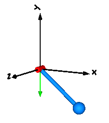
The world coordinate system is visualized as coordinate system with axes labels. The direction of the gravity acceleration vector is shown as green arrow. The red cylinder represents the rotation axis of the revolute joint and the light blue shapes represent the body. The center of mass of the body is in the middle of the light blue sphere.