WOLFRAM SYSTEM MODELER
PlanarLoopsPlanar loops |
|
Wolfram Language
In[1]:=
SystemModel["Modelica.Mechanics.MultiBody.UsersGuide.Tutorial.LoopStructures.PlanarLoops"]
Out[1]:=
Information
This information is part of the Modelica Standard Library maintained by the Modelica Association.
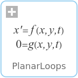
In the figure below, the model of a V6 engine is shown that has a simple combustion model. It is available as MultiBody.Examples.Loops.EngineV6.
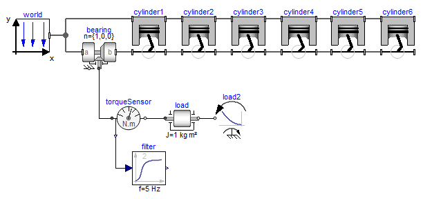
The Modelica schematic of one cylinder is given in the figure below. Connecting 6 instances of this cylinder appropriately together results in the engine schematic displayed above.
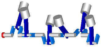
In the next figure the animation of the engine is shown. Every cylinder consists essentially of 1 prismatic and 2 revolute joints that form a planar loop, since the axes of the two revolute joints are parallel to each other and the axis of the prismatic joint is orthogonal to the revolute joint axes. All 6 cylinders together form a coupled set of 6 loops that have together 1 degree of freedom.
All planar loops, and especially the engine, result in a DAE (= Differential-Algebraic Equation system) that does not have a unique solution. The reason is that, e.g., the cut forces in direction of the axes of the revolute joints cannot be uniquely computed. Any value fulfills the DAE equations. This is a structural property that is determined by the symbolic algorithms. Since they detect that the DAE is structurally singular, a further processing is not possible. Without additional information it is also impossible that the symbolic algorithms could be enhanced because if the axes of rotations of the revolute joints are only slightly changed such that they are no longer parallel to each other, the planar loop can no longer move and has 0 degrees of freedom. Algorithms based on pure structural information cannot distinguish these two cases.
The usual remedy is to remove superfluous constraints, e.g., along the axis of rotation of one revolute joint. Since this is not easy for an inexperienced modeler, the special joint: RevolutePlanarLoopConstraint is provided that removes these constraints. Exactly one revolute joint in a every planar loop must be replaced by this joint type. In the engine example, this special joint is used for the revolute joint B2 in the cylinder model above. The icon of the joint is slightly different to other revolute joints to visualize this case.
If a modeler is not aware of the problems with planar loops and models them without special consideration, a Modelica translator displays an error message and points out that a planar loop may be the reason and suggests to use the RevolutePlanarLoopConstraint joint. This error message is due to an annotation in the Frame connector.
connector Frame
   ...
   flow SI.Force f[3] annotation(unassignedMessage="...");
end Frame;
If no assignment can be found for some forces in a connector, the "unassignedMessage" is displayed. In most cases the reason for this is a planar loop or two joints that constrain the same motion. Both cases are discussed in the error message.
Note, that the non-linear algebraic equations occurring in planar loops can be solved analytically in most cases and therefore it is highly recommended to use the techniques discussed in section "Analytic loop handling" for such systems.