Embed a dynamic system for hardware-in-the loop simulation
Introduction
Hardware-in-the-loop (HIL) simulation is a simulation that uses a mathematical model of the physical system in a real-time environment. This is especially useful in scenarios when the physical system is inaccessible for cost or safety reasons. Because of the real-time nature of the simulation, a controller or person will be essentially interacting with the physical system if the mathematical model is of adequate fidelity. Typical applications of HIL simulation are in testing controllers before deploying them to control the actual physical system, in analyzing the physical system, and in training.
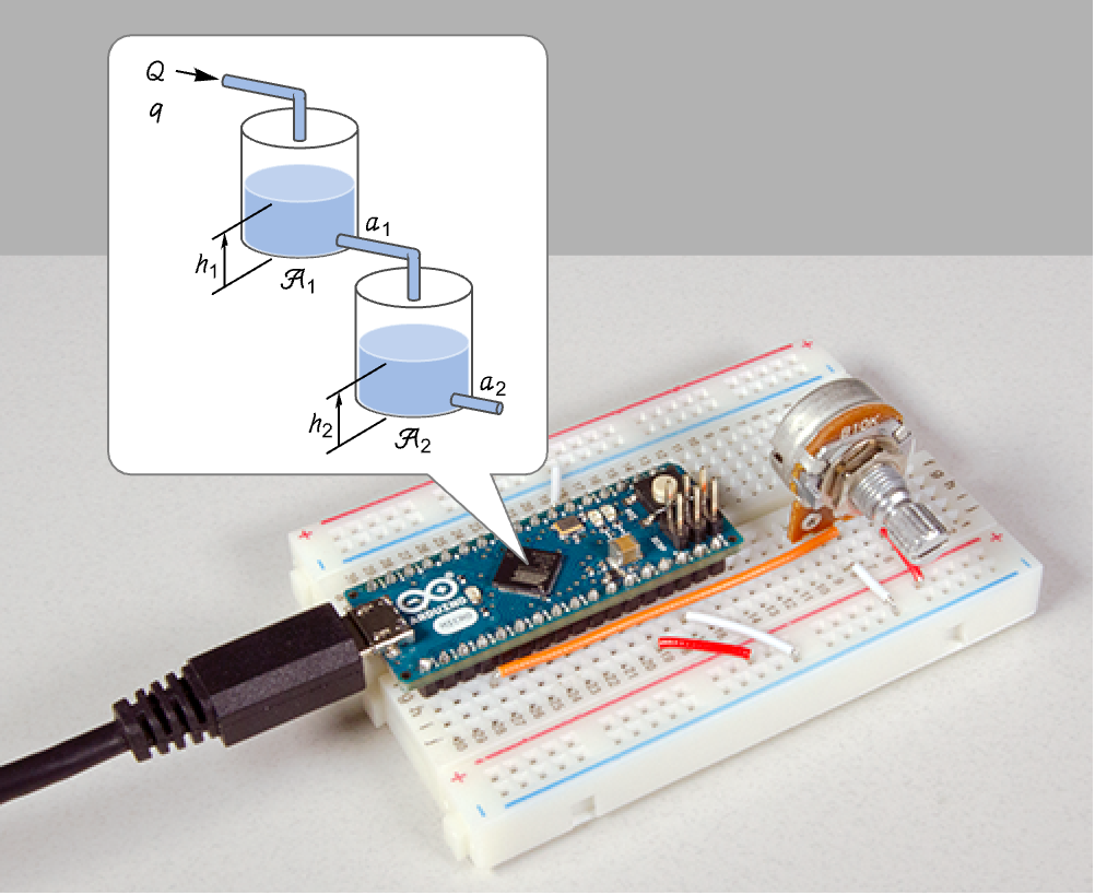
In this project, we will deploy the nonlinear model of a two-tank system to an Arduino Micro microcontroller board. The input to the system is the flow rate into the upper tank. This controls the liquid levels which will be considered as the outputs. A potentiometer will be used to adjust the flow rate, and the liquid levels will be output as serial-over-usb signals. This can then be read using the device framework. Thus we can simulate and analyze the behavior of the two-tank system in real-time.
Electrical wirings
Connect the wiper terminal of the potentiometer to pin A0 and one terminal to GND and the other to 5V.
The Arduino Micro must also be connected to the computer using a micro USB cable.
Mathematical model
In the two-tank system, the flow into the upper tank is used to control the liquid levels in both tanks.
The physical parameters of the system.
Use Bernoulli's law and mass balance to derive the resulting differential equations.
Use steady-state operating values ![]() .
.
Define the corresponding nonlinear system with input ![]() and outputs
and outputs ![]() and
and ![]() .
.
Embed the model
Discretize the model with a sampling period of 0.25 seconds:
The input flow is controlled by a potentiometer and the flow is scaled to vary from 1 to 2:
Set up the model to return the input flow along with the heights in the two tanks.
Load the package.
Embed the model:
Read the simulated signals
Open a serial connection to the target:
The start, delimiter, and end bytes.
A function to parse the data coming though the serial connection:
Set up a task to read the values every second (and apply a step input using the potentiometer):
Remove the task and terminate the device connectionafter about 30 minutes:
The height of the liquid in the two tanks to a step input from the potentiometer:
Retrieve the step input that was applied to the system:
Compare the real-time and simulated results:
We see that the real-time simulation results are on par with that of the simulation in the Wolfram system. However, the real-time simulation was running for the approximately 30 minutes that it took for the liquid levels to rise from 2.7 meters to 3.3 meters when the flow rate was increased from 1 ![]() to 1.11
to 1.11 ![]() .
.
More things to try
- Try other ways to visualize the liquid levels.
- Send the output signals using some other channel.
- Simulate disturbances to the liquid levels.
- Design a controller that regulates the liquid levels and do a HIL simulation.
- Do a HIL simulation of another system like a simple pendulum, a DC motor, etc.