3D Print and Mechanical Design
Introduction
3D printing enables rapid creation of complex, customized objects without traditional tooling, making it ideal for prototyping of functional parts. However, when printed components must withstand real-world loads, mechanical optimization becomes essential.
This is where Finite Element Analysis (FEA) comes in. FEA simulates how a design behaves under stress, allowing engineers to identify weak points, optimize geometry and reduce weight before printing. By integrating FEA into the design process, one can ensure that 3D-printed parts are both efficient and structurally good.
In this application, a hook is designed to meet specific constraints in terms of geometry and load-bearing capacity. Given that the final component is intended to be 3D printed in polylactic acid (PLA), particular attention must be paid to the mechanical properties of the material and the structural integrity of the design.
Due to the inherent limitations of polymer-based additive manufacturing, such as lower strength, anisotropy and potential for layer delamination, the use of FEA becomes essential. FEA allows for the evaluation and optimization of the hook under realistic loading conditions, ensuring that the final printed part is both safe and functionally reliable within a given specification.
Design Requirements
The primary design constraints for the hook include the position and diameter of the fixation holes, as well as the maximum allowable spacing between the fixation surface and the opposite extremity, referred to as the side in the figure below. The hook must be capable of withstanding a predefined load of 1200 [N], while allowing only minimal displacements. Although some deformation is acceptable, it should be kept as low as possible to ensure functional stability.
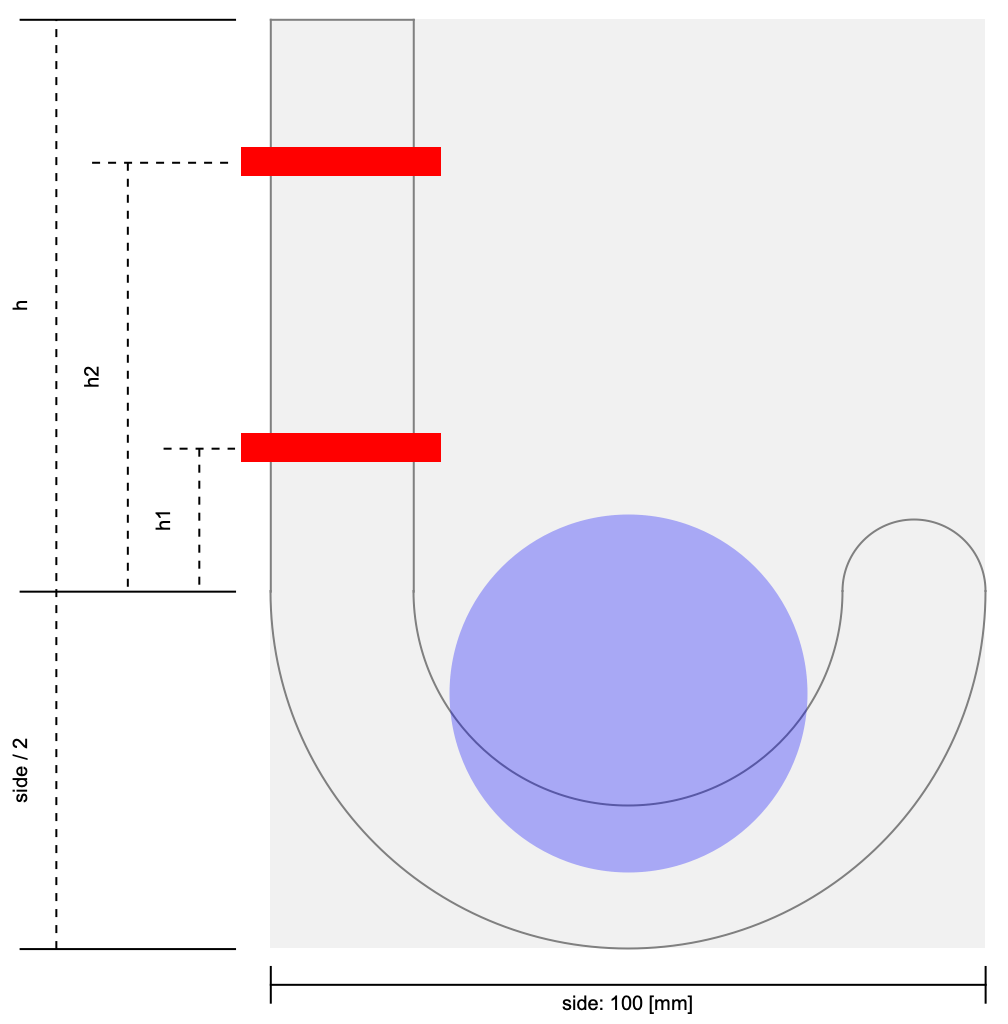
Geometric constraints of the hook design.
A key objective is to minimize material usage, taking into account the infill settings and limitations of the 3D printing process. Infill settings define the internal structure of a printed part in terms of density, percentage of solid material and a pattern, like grid, honeycomb, gyroid. By adjusting these parameters, it is possible to significantly reduce weight, save material and shorten print time. This optimization comes with a tradeoff: lower infill can compromise strength and stiffness. So a proper mechanical analysis during the design phase is essential to ensure that the printed part meets the required performance criteria without overusing material.
Furthermore, the design must maintain a safe margin relative to the tensile strength of the polylactic acid (PLA) filament to prevent material failure. In summary, the goal is to maximize the strength-to-weight ratio of the hook, ensuring a good balance between mechanical performance and material efficiency.
side = 100;
r = side / 2;
t = 20;
height = 80;
h1 = 20;
h2 = 60;
width = 20;
rh = 5;
In the following sections, three different hook designs are proposed and analyzed using FEA. Given that 3D-printed objects can be fabricated with varying infill properties, such as shape, density and orientation, the influence of infill characteristics on mechanical performance is also investigated.
The use of FEA allows for a detailed comparison of the structural behavior of each design, helping to identify the most effective solution in terms of strength, stiffness and material efficiency. All CAD models were developed using OpenCascadeLink, ensuring precise control over geometry and parameterization.
Design Alternatives
The three proposed designs are based on a common conceptual approach: each starts from a 2D profile, which is then extruded to the required width to form the final 3D geometry. While these three configurations represent distinct alternatives, they are part of a much broader design space, potentially encompassing an infinite number of variations in shape, thickness, curvature and structural features. The selected designs aim to explore meaningful tradeoffs between material usage, strength and manufacturability, serving as representative cases for performance evaluation.
Needs["OpenCascadeLink`"]
Needs["NDSolve`FEM`"]
Version A: Monolithic Curved Hook
The 2D base profile consists of a rectangular section aligned with the fixation holes, followed by a half-circular arc that defines the hook’s shape, ending in a smoothly rounded tip to complete the geometry.
union = OpenCascadeShapeUnion[OpenCascadeShape[#]& /@ {
	Circle[{r, 0}, r, {-π, 0}],
	Line[{{0, 0}, {0, height}}],
	Line[{{0, height}, {t, height}}],
	Line[{{t, height}, {t, 0}}],
	Circle[{r, 0}, r - t, {-π, 0}],
	Circle[{2r - t / 2, 0}, t / 2, {0, π}]
	}];
union = OpenCascadeShapeFace[union];OpenCascadeShapeSurfaceMeshToBoundaryMesh[union]["Edgeframe"]direction = {{0, 0, 0}, {0, 0, width}};sweep = OpenCascadeShapeLinearSweep[union, direction];OpenCascadeShapeSurfaceMeshToBoundaryMesh[sweep]["Wireframe"]Once the 2D profile is defined, it is extruded through a linear sweep to achieve the desired width. The resulting sharp edges are then rounded with a fillet radius equal to 30% of the total width, ensuring smoother transitions and improved mechanical performance.
shape1 = OpenCascadeShapeFillet[sweep, 0.3width];Show[
OpenCascadeShapeSurfaceMeshToBoundaryMesh[shape1]["Wireframe"]
]Version B: Compact Reinforced Hook
The second design features a slim profile, enhanced by a reinforcement rib positioned at the bottom corner, between the curved, load-bearing section and the vertical fixation wall, to improve structural rigidity and distribute stress more effectively. This reinforcement is incorporated directly into the 2D profile before extrusion, followed by a Boolean subtraction in the 3D geometry to reduce material usage while maintaining strength.
t2 = 12;union = OpenCascadeShapeUnion[OpenCascadeShape[#]& /@ {
Circle[{r, 0}, r, {-π / 2, 0}],
Line[{{0, -r}, {0, height}}],
Line[{{0, height}, {t2, height}}],
Line[{{t2, height}, {t2, 0}}],
Circle[{r, 0}, r - t2, {-π, 0}],
Circle[{2r - t2 / 2, 0}, t2 / 2, {0, π}],
Line[{{0, -r}, {r, -r}}]
}];
union = OpenCascadeShapeFace[union];OpenCascadeShapeSurfaceMeshToBoundaryMesh[union]["Edgeframe"]sweep = OpenCascadeShapeLinearSweep[union, direction];face = OpenCascadeShape[RegionDifference[
Rectangle[{t2 / 2, -r + t2 / 2}, {r - t2 / 2, -t}],
Disk[{r, 0}, r - t2 + t2 / 2]
]];
sweep2 = OpenCascadeShapeLinearSweep[face, direction];Show[OpenCascadeShapeSurfaceMeshToBoundaryMesh[sweep]["Wireframe"], OpenCascadeShapeSurfaceMeshToBoundaryMesh[sweep2]["Wireframe"["MeshElementStyle" -> FaceForm[Red]]]]shape2 = OpenCascadeShapeDifference[sweep, sweep2];Show[
OpenCascadeShapeSurfaceMeshToBoundaryMesh[shape2]["Wireframe"]
]Version C: Angular Frame Hook
The third design adopts a sharper geometry, characterized by a 90-degree angle between the anchoring section and the load-bearing side, resulting in a more angular and rigid structure compared to the previous curved designs.
union = OpenCascadeShapeUnion[OpenCascadeShape[#]& /@ {
	Line[{{0, -0.8r}, {0, height}}],
	Line[{{0, height}, {t2, height}}],
	Line[{{t2, height}, {t2, -0.8r + t2}}],
	Line[{{t2, -0.8r + t2}, {2r - t2, -0.8r + t2}, {2r - t2, -0.8r + 2t2}, {2r, -0.8r + 2t2}, {2r, -0.8r}, {0, -0.8r}}]
	}];
union = OpenCascadeShapeFace[union];OpenCascadeShapeSurfaceMeshToBoundaryMesh[union]["Edgeframe"]sweep3 = OpenCascadeShapeLinearSweep[union, direction];shape3 = OpenCascadeShapeFillet[sweep3, t2 / 2, {1, 10, 18, 26, 6}];OpenCascadeShapeSurfaceMeshToBoundaryMesh[shape3]["Wireframe"]Fixation Holes
Finally, the fixation holes are created by subtracting cylindrical volumes from the solid body, ensuring precise positioning and consistent dimensions in the final geometry.
holes = OpenCascadeShape[
	RegionUnion[Cylinder[{{-t, #, width / 2}, {t + 1, #, width / 2}}, rh],
Cone[{{t * 1.2, #, width / 2}, {0, #, width / 2}}, 1.8rh]]]& /@ {h1, h2}Show[
OpenCascadeShapeSurfaceMeshToBoundaryMesh[shape1]["Wireframe"],
OpenCascadeShapeSurfaceMeshToBoundaryMesh[#]["Wireframe"["MeshElementStyle" -> Directive[Opacity[0.8], FaceForm[Red]]]]& /@ holes
]hook1 = OpenCascadeShapeDifference[shape1, holes];holes = OpenCascadeShape[
RegionUnion[Cylinder[{{-t, #, width / 2}, {t2 + 1, #, width / 2}}, rh],
Cone[{{t2 * 1.2, #, width / 2}, {0, #, width / 2}}, 1.8rh]]]& /@ {h1, h2};hook2 = OpenCascadeShapeDifference[shape2, holes];
hook3 = OpenCascadeShapeDifference[shape3, holes];hookBmeshes = OpenCascadeShapeSurfaceMeshToBoundaryMesh[#, "ShapeSurfaceMeshOptions" -> {"LinearDeflection" -> 0.001}, "ElementMeshOptions" -> {"LengthUnit" -> "Meters"}]& /@ {hook1, hook2, hook3};GraphicsRow[Show[#["Wireframe"["MeshElementStyle" -> Directive[FaceForm[Gray], EdgeForm[]]]]]& /@ hookBmeshes]Finite Element Analysis
Before conducting FEA on the three proposed hook designs, it is essential to understand how infill choices affect the mechanical properties of 3D-printed parts. In fused deposition modeling (FDM) printing, users can define the infill pattern and density, which directly influence not only material usage and weight but also the structural stiffness and strength of the printed object.
To avoid the high computational cost of modeling the infill geometry in detail throughout the entire object, a common approach known as homogenization is adopted. This method involves studying the mechanical behavior of simplified 2D or 3D infill samples to extract effective material properties. These equivalent, homogenized properties can then be used in FEA simulations of the full part, enabling accurate predictions of mechanical performance without resolving the detailed infill structure [1].
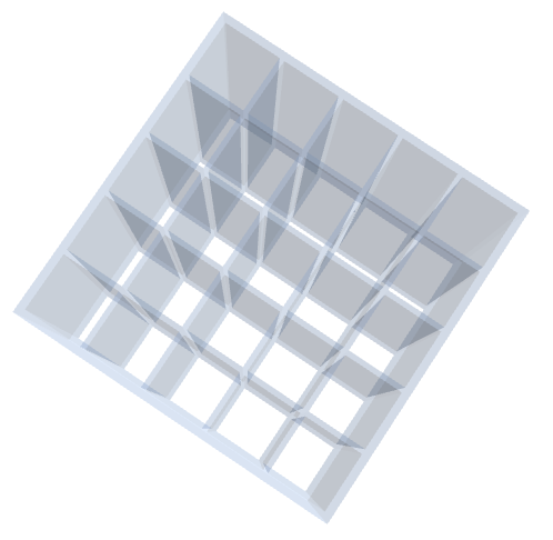
Rectangular grid infill for 3D print.
The hook design is intended to be manufactured using PLA, a widely used thermoplastic in FDM 3D printing. PLA offers good dimensional stability, ease of printing and biodegradability, making it suitable for structural parts under moderate loading conditions.
For mechanical analysis, the following material properties are considered based on typical values found in the literature and datasheets: Young modulus of 3,500 [![]() ], tensile limit of 60 [
], tensile limit of 60 [![]() ], a Poisson ratio of 0.3 and a density of 1.25 [
], a Poisson ratio of 0.3 and a density of 1.25 [![]() ] [2].
] [2].
YPla = 3500 * 10^6;
νPla = 0.3;
σlimPla = 60 * 10^6;
ρPla = 1.25 * 10^3 ;(*kg / m^3*)
Infill Properties
The variety of possible infill patterns in 3D printing is virtually infinite, including rectilinear, triangular, hexagonal or honeycomb, gyroid and concentric structures. However, for the sake of simplicity and consistency, this study focuses exclusively on a rectangular grid infill pattern.
The primary objective of this analysis is to evaluate the effect of infill density on the mechanical behavior of printed parts. To that end, the infill is modeled as a periodic, extrusion-like geometry, allowing its behavior to be represented using a 2D slice under plane strain conditions in the Finite Element Analysis (FEA).
Infill Representation
Moreover, since the study is focused on relative mechanical properties, like stiffness versus density, the actual physical size of the infill unit can be treated as dimensionless or generic without loss of generality.
lineWidth = 0.8;
ratio = 5;
size = 50;
border = 3;createRectangularInfill[ratio_] := Module[
{space, reg, list, lw = lineWidth},
space = size / ratio;
list = Flatten@{Table[
Table[Rectangle[{x + lw / 2, y + lw / 2}, {x + space - lw / 2, y + space - lw / 2}],
{x, 0, size - lw, space}], {y, 0, size - lw, space}]};
reg = Rectangle[{0 - border * lw, 0 - border * lw}, {size + border * lw, size + 5 border * lw}];
reg = Fold[RegionDifference, reg, list];
reg
]The rectangular infill pattern can be generated based on the ratio between rectangle size and the internal cell size.
regs = createRectangularInfill[#]& /@ {2, 3, 5, 8, 12, 16, 20, 30, 40};AppendTo[regs, Region@Rectangle[{-border * lineWidth, -border * lineWidth}, {size + border * lineWidth, size + 5border * lineWidth}]];Grid[Partition[Region /@ regs, 5]]Load Scheme
For the loading scheme, the base of the sample is considered fixed, with a vertical force applied from above to induce compression.
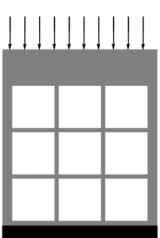
To simulate a general compression load more realistically, the top surface can be modeled as a stiffer region or rigid body. This approach helps limit excessive local deformations that would not typically occur in a physical test setup using a clamping plate or compression platen.
Finite Element Analysis
vars = {{u[x, y], v[x, y]}, {x, y}};pars = <|"YoungModulus" -> If[y <= size + border * lineWidth, YPla, 100 * YPla], "PoissonRatio" -> νPla, "Thickness" -> size, "SolidMechanicsModel" -> "PlaneStrain"|>;force = -50 * 10^10;solveFEMProblem[reg_] := Module[
{mesh, displacement, bounds, pde},
mesh = ToElementMesh[reg, "MaxCellMeasure" -> 0.05];
bounds = mesh["Bounds"];
pde = {SolidMechanicsPDEComponent[vars, pars] ==
SolidBoundaryLoadValue[y == bounds[[-1, -1]], vars, pars, <|"Force" -> {None, force}|>],
SolidDisplacementCondition[y == bounds[[-1, 1]], vars, pars, <|"Displacement" -> {0, 0}|>]
};
displacement = NDSolveValue[pde, vars, vars[[-1]]∈mesh];
{mesh, displacement}
]Results
results = solveFEMProblem[#]& /@ regs;meshZoom = Show[#["Wireframe"], "PlotRange" -> {{All, size / 8}, {All, size / 9}}]& /@ results[[All, 1]];
Grid[Partition[meshZoom, 5]]It is important to note that the mesh is refined enough to provide several elements across each segment of the infill, ensuring a precise and accurate numerical solution. As expected, reducing the infill density leads to an increase in displacement, due to the lower overall stiffness of the structure.
deformedMeshes = ElementMeshDeformation[#[[1]], #[[2, 1]], "ScalingFactor" -> 1]& /@ results;Grid@Partition[Show[#["Edgeframe"],
Graphics@{FaceForm[], EdgeForm[Red], Rectangle[{0 - border * lineWidth, 0 - border * lineWidth}, {size + border * lineWidth, size + 5border * lineWidth}]}
]& /@ deformedMeshes, 5]The results of this numerical analysis are consistent with findings reported in the literature, particularly the Gibson–Ashby model [3], which describes a second-order relationship between relative stiffness and relative density, the infill ratio. In the context of a linear elastic material, stiffness can be interpreted as the ratio between applied force and resulting displacement. Since the applied load remains constant across simulations, the relative stiffness is inversely proportional to the observed displacement.
modelGAcoeff = {x, x ^ 2};area = NIntegrate[1, {x, y}∈#]& /@ results[[All, 1]]infill = (area/area[[-1]])maxDispl = Abs@Min[Head[#[[1, 2]]]["ValuesOnGrid"]]& /@ results[[All, 2]];stiffness = (1/maxDispl / Min[maxDispl]);modelGA = Fit[Transpose[{infill, stiffness}], modelGAcoeff, x]Show[
Plot[modelGA, {x, 0.1, 1.1}, ...],
ListPlot[Transpose[{infill, stiffness}], Rule[...]]
]The numerical results align well with the Gibson–Ashby model, validating the observed trend between infill density and structural stiffness. Based on this correspondence, a homogenized stiffness value equal to 60% of the base material’s stiffness is selected for the subsequent FEA simulations of the hook designs.
Design Test
After establishing the relationship between infill ratio and material stiffness, a Solid Mechanics analysis can be conducted on the proposed designs to evaluate their mechanical performance. The process begins with the conversion of each shape into an ElementMesh. Once variables and material properties are defined, the boundary conditions are set, including constraints on the mounting holes, the wall behind the hook and the applied load.
hooks = ToElementMesh[#]& /@ hookBmeshes;toMM = 10^-3;vars = {{u[x, y, z], v[x, y, z], w[x, y, z]}, {x, y, z}};infillFactor = 0.6;pars = <|"YoungModulus" -> infillFactor * YPla, "PoissonRatio" -> νPla|>;wallCondition = x == 0;holesCondition = ((y - toMM h1)^2 + (z - toMM width / 2)^2 <= (toMM 1.8rh)^2 || (y - toMM h2)^2 + (z - toMM width / 2)^2 <= (toMM 1.8rh)^2)hookLoad = -0.3 * 10^3;loadCondition = (x - toMM r)^2 + (y + toMM r / 3.5)^2 <= (toMM r / 2)^2loadNodes = Select[#["Coordinates"], (#[[1]] - toMM * r) ^ 2 + (#[[2]] + toMM * r / 3.5) ^ 2 <= (toMM * r / 2) ^ 2&]& /@ hooks;
fixedNodes = Select[#["Coordinates"], (#[[2]] - toMM h1)^2 + (#[[3]] - toMM width / 2)^2 <= (toMM 1.8rh)^2 || (#[[2]] - toMM h2)^2 + (#[[3]] - toMM width / 2)^2 <= (toMM 1.8rh)^2&]& /@ hooks;
wallNodes = Select[#["Coordinates"], (#[[1]] == 0)&]& /@ hooks;
GraphicsRow[Table[Show[
hooks[[i]]["Wireframe"["MeshElementStyle" -> Directive[FaceForm[Gray], EdgeForm[]]]], Graphics3D[{Red, Point[loadNodes[[i]]], Blue, Point[fixedNodes[[i]]], Black, Point[wallNodes[[i]]]}]], {i, 1, Length[hooks]}]]It is important to note that the mounting holes and the loaded zone are identical across all shapes. This allows the partial differential equations to be defined once and subsequently solved over the three different meshes.
pde = {
	SolidMechanicsPDEComponent[vars, pars] ==
	SolidBoundaryLoadValue[loadCondition, vars, pars, <|"Force" -> {0, hookLoad, 0}|>],
	SolidDisplacementCondition[wallCondition, vars, pars, <|"Displacement" -> {0, None, None}|>],
	SolidFixedCondition[holesCondition, vars, pars]
	};
Finally, it is now possible to compute the solution in terms of displacement. Additionally, options are introduced in the "ExtrapolationHandler" to suppress warning messages. This will be particularly useful in the next steps, where the computed displacements will be used to deform the original geometries, not just the ElementMesh. In such cases, small discrepancies between geometry and mesh nodes may trigger warning messages, which can be silenced.
displacements = NDSolveValue[pde, {u[x, y, z], v[x, y, z], w[x, y, z]}, {x, y, z}∈#, "ExtrapolationHandler" -> {Automatic, "WarningMessage" -> False}]& /@ hooks;defMeshes = ElementMeshDeformation[hooks[[#]], displacements[[#]], "ScalingFactor" -> 2]& /@ Range[Length[hooks]];GraphicsRow[Show[
hooks[[#]]["Wireframe"["MeshElementStyle" -> Directive[Opacity[0.2], EdgeForm[], FaceForm[Gray]]]], defMeshes[[#]]["Wireframe"["MeshElementStyle" -> Directive[Opacity[0.8], EdgeForm[], FaceForm[Gray]]]]
, ViewPoint -> Top]& /@ Range[Length[hooks]]]After evaluating the displacement, several post-processing quantities can provide valuable insights. In particular, the stress distribution serves as an indicator of how close the material is to its failure point. Lower stress values generally correspond to safer designs.
postProcess[displ_] := Module[{strain, stress, vm},
	strain = SolidMechanicsStrain[vars, pars, displ];
	stress = SolidMechanicsStress[vars, pars, strain];
	vm = VonMisesStress[vars, pars, stress];
	{strain, stress, vm}
]secondaryQuantities = postProcess[#]& /@ displacements;vmList = secondaryQuantities[[All, 3]];defVmList = ElementMeshInterpolation[defMeshes[[#]], Head[vmList[[#]]]["ValuesOnGrid"], "ExtrapolationHandler" -> {Automatic, "WarningMessage" -> False}][x, y, z]& /@ Range[Length[hooks]];halves = OpenCascadeShapeSurfaceMeshToBoundaryMesh[OpenCascadeShapeIntersection[#,
OpenCascadeShape[Cuboid[{-r, -r, 0}, {3r, height, t / 2}]]], "ElementMeshOptions" -> {"LengthUnit" -> "Meters"}, "ShapeSurfaceMeshOptions" -> {"LinearDeflection" -> 0.001}]& /@ {hook1, hook2, hook3};In addition, each geometry is symmetric with respect to its central plane, allowing the structure to be halved for visualization purposes. Displaying stress and deformation on a single half provides clearer insights into stress distribution and potential failure zones, particularly around hole boundaries. While this can be challenging due to the use of 3D tetrahedral meshes, it is possible to leverage the predefined OpenCascadeShape. These CAD-based shapes can be easily sliced by intersecting them with a cuboid defined over the region of interest. The resulting shape can then be converted back into a region, and the same displacement field can be applied to move each node, enabling visualization of the final deformed configuration.
deformedHalfAsRegion[displ_, mesh_, breg_, scale_] := Module[{cc, ee, dx, dy, dz, newreg, dxfun, dyfun, dzfun},
		  cc = MeshCoordinates[breg];
		  ee = MeshCells[breg, 2];
		  {dxfun, dyfun, dzfun} = Head[#] & /@ displ;
		   dx = scale * (dxfun @@@ cc);
		  dy = scale * (dyfun @@@ cc);
	            dz = scale * (dzfun @@@ cc);
		  newreg = BoundaryMeshRegion[cc + Transpose[{dx, dy, dz}], ee];
		  newreg
]defHalfRegs = deformedHalfAsRegion[displacements[[#]], hooks[[#]], BoundaryMeshRegion[halves[[#]]], 2]& /@ Range[Length[hooks]];stressImgs = Show[hooks[[#]][...], SliceDensityPlot3D[defVmList[[#]], defHalfRegs[[#]], {x, y, z}∈defHalfRegs[[#]], ...]]& /@ Range[Length[hooks]];GraphicsRow[{GraphicsColumn[stressImgs], BarLegend[{"TemperatureMap", slim}, LegendLayout -> "Column", LegendLabel -> "von Mises stress"]}, ImageSize -> Large]The safety factor for structural integrity depends on several design considerations, including material properties, loading conditions, geometric complexity and manufacturing method. In the context of this design, a safety factor of 80% is adopted, meaning the maximum allowable stress is limited to 80% of the material’s yield strength. This conservative margin accounts not only for uncertainties in loading and boundary conditions, but also for material variability introduced by additive manufacturing. Specifically, in 3D printed components, the effective strength can be significantly lower than that of bulk material due to weaker interlayer bonding. In some cases, the failure stress may be reduced to as low as 10% of the yield strength of solid PLA, particularly when anisotropy and poor adhesion between layers are present.
safetyFactor = 0.8;stressLimit = 0.1σlimPla;safety = ElementMeshInterpolation[defMeshes[[2]], If[# > safetyFactor stressLimit, 0, 1]& /@ Head[defVmList[[2]]]["ValuesOnGrid"]][x, y, z];GraphicsRow[{Show[SliceContourPlot3D[
safety, defHalfRegs[[2]], {x, y, z}∈defHalfRegs[[2]], ...], hooks[[2]][...]], SwatchLegend[...]}, Rule[...]]As shown in the images, this design is quite safe in terms of maximum stress. Additionally, it appears to have the smallest deflection among the options.
weight = NIntegrate[2 * infillFactor ρPla, {x, y, z}∈#]& /@ defHalfRegs;vMax = Abs[Min[Head[#[[2]]]["ValuesOnGrid"]]]& /@ displacements;swratio = (1/vMax weight );Show[
ListLinePlot[swratio, ...],
ListPlot[...]]In conclusion, this design offers the best stiffness-to-weight ratio, delivering twice the performance of the first option. The third design is excluded due to its relatively high stress levels.
References
1. Liu, X. et. al. (2016) "Homogenization of Material Properties in Additively Manufactured Structures." Computer-Aided Design. Volume 78 (15–16). http://dx.doi.org/10.1016/j.cad.2016.05.017.
2. Tymrak, B.M. et. al. (2014) "Mechanical Properties of Components Fabricated with Open-Source 3-D Printers under Realistic Environmental Conditions." Materials & Design. Volume 58, June 2014, 242–246. https://doi.org/10.1016/j.matdes.2014.02.038.
3. Maconachie, T. et. al. "SLM Lattice Structures: Properties, Performance, Applications and Challenges." Materials & Design. Volume 183, 5 December 2019, 108137. https://doi.org/10.1016/j.matdes.2019.108137.