WOLFRAM SYSTEM MODELER
AutopilotBaseInterface for autopilot |
|
Diagram
Wolfram Language
In[1]:=
SystemModel["Aircraft.Autopilots.Interfaces.AutopilotBase"]
Out[1]:=
Information
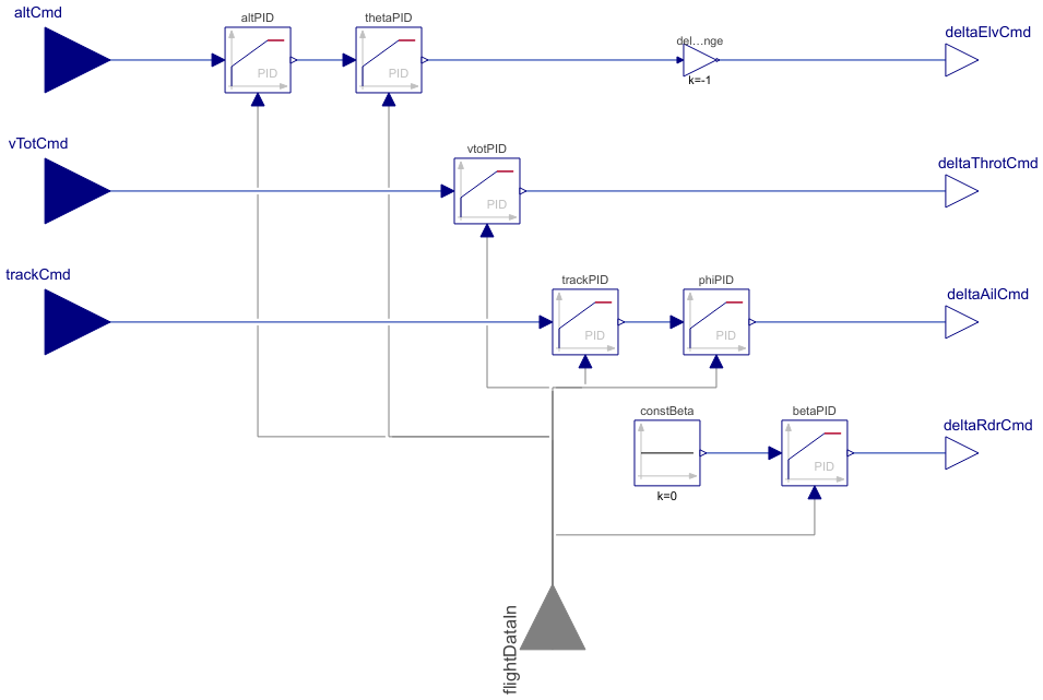
This class is the autopilot base model, which the autopilot models designed for different aircraft types extend. This autopilot model translates the commands that are used to define a reference flight trajectory, namely altitude, total velocity and track angle, into control actuator commands for an aircraft with conventional wing configuration, which includes elevator, ailerons and rudder deflection angles, as well as a command for throttle position. The autopilot architecture is shown in Figure 1 with its six PID controllers and surrounding models for actuator and aircraft dynamics.

Figure 1: Autopilot architecture. [1]
The altitude is controlled by the elevator deflection (δe) with two LimPID controllers in series, of which the first outputs a reference pitch angle (θref) based on the error between the measured and reference altitudes, and the second outputs the δe based on the error between the measured and reference pitch angles. Similarly, the track angle is controlled by the ailerons deflection (δa) with two LimPID controllers in series, of which the first outputs a reference roll angle (φref) for the second, which outputs the δa. The reference pitch and roll angles can be constrained by the maxTheta and maxPhi parameters, respectively.
The total velocity is controlled by the throttle position (δT) with one LimPID controller. The rudder deflection (δr) is used to control the sideslip angle (β) from a constant zero signal as the reference sideslip angle, i.e. the rudder is only used to minimize the sideslip angle in order to reduce drag and lateral accelerations.
This autopilot model can also be used to partially control only the selected actuators by disabling control of the other actuators by the elvControl, throtControl, ailControl and rdrControl parameters in the Control Settings tab. All control gains of the LimPID controllers are gathered to the Control Gains parameter tab.
The measured altitude, total velocity and track, pitch, roll and sideslip angles are inputs to this model through the FlightDataIn connector.
References
[1] Erä-Esko, N. (2022). "Development and Use of System Modeler 6DOF Flight Mechanics Model in Aircraft Conceptual Design."
Available at: modelica://Aircraft/Resources/Documents/EraeEskoThesis.pdf.
Parameters (24)
| elvControl |
Value: Type: Boolean Description: true, if elevator is controlled |
|---|---|
| throtControl |
Value: Type: Boolean Description: true, if throttle is controlled |
| ailControl |
Value: Type: Boolean Description: true, if ailerons are controlled |
| rdrControl |
Value: Type: Boolean Description: true, if rudder is controlled |
| maxPhi |
Value: Type: Angle (rad) Description: Maximum roll angle |
| maxTheta |
Value: Type: Angle (rad) Description: Maximum pitch angle |
| altPIDk |
Value: Type: Real Description: Altitude PID Gain |
| altPIDTi |
Value: Type: Time (s) Description: Altitude PID Integrator Block |
| altPIDTd |
Value: Type: Time (s) Description: Altitude PID Derivative Block |
| thetaPIDk |
Value: Type: Real Description: Theta PID Gain |
| thetaPIDTi |
Value: Type: Time (s) Description: Theta PID Integrator Block |
| thetaPIDTd |
Value: Type: Time (s) Description: Theta PID Derivative Block |
| vtotPIDk |
Value: Type: Real Description: Velocity PID Gain |
| vtotPIDTi |
Value: Type: Time (s) Description: Velocity PID Integrator Block |
| vtotPIDTd |
Value: Type: Time (s) Description: Velocity PID Derivative Block |
| trackPIDk |
Value: Type: Real Description: Track PID Gain |
| trackPIDTi |
Value: Type: Time (s) Description: Track PID Integrator Block |
| trackPIDTd |
Value: Type: Time (s) Description: Track PID Derivative Block |
| phiPIDk |
Value: Type: Real Description: Phi PID Gain |
| phiPIDTi |
Value: Type: Time (s) Description: Phi PID Integrator Block |
| phiPIDTd |
Value: Type: Time (s) Description: Phi PID Derivative Block |
| betaPIDk |
Value: Type: Real Description: Beta PID Gain |
| betaPIDTi |
Value: Type: Time (s) Description: Beta PID Integrator Block |
| betaPIDTd |
Value: Type: Time (s) Description: Beta PID Derivative Block |
Connectors (8)
| deltaElvCmd |
Type: RealOutput Description: Elevator deflection command |
|
|---|---|---|
| deltaThrotCmd |
Type: RealOutput Description: Throttle position command |
|
| altCmd |
Type: RealInput Description: Altitude command |
|
| vTotCmd |
Type: RealInput Description: Total velocity command |
|
| deltaRdrCmd |
Type: RealOutput Description: Rudder deflection command |
|
| deltaAilCmd |
Type: RealOutput Description: Aileron deflection command |
|
| trackCmd |
Type: RealInput Description: Track command |
|
| flightDataIn |
Type: FlightDataIn Description: Flight data input |
Components (8)
| altPID |
Type: LimPID Description: PID controller from altitude command to pitch angle (theta) command |
|
|---|---|---|
| vtotPID |
Type: LimPID Description: PID controller from total velocity command to throttle position command |
|
| trackPID |
Type: LimPID Description: PID controller from track angle command to roll angle (phi) command |
|
| betaPID |
Type: LimPID Description: PID controller from sideslip angle command to rudder deflection command |
|
| phiPID |
Type: LimPID Description: PID controller from roll angle (phi) command to aileron deflection command |
|
| thetaPID |
Type: LimPID Description: PID controller from pitch angle (theta) command to elevator deflection command |
|
| constBeta |
Type: Constant Description: Constant 0 signal to Beta PID setpoint input |
|
| deltaElvSignChange |
Type: Gain Description: Sign change for elevator deflection command |
Extended by (5)
|
Aircraft.Autopilots Autopilot for gliders |
|
|
Aircraft.Autopilots Autopilot for light aircraft with electric propulsion |
|
|
Aircraft.Autopilots Autopilot for passenger aircraft with turbofan propulsion |
|
|
Aircraft.Autopilots Autopilot for passenger aircraft with turboprop propulsion |
|
|
Aircraft.Autopilots Autopilot for light aircraft with piston engine propulsion |