WOLFRAM SYSTEM MODELER
ConventionalPropulsionInterface for conventional propulsion model |
|
Diagram
Wolfram Language
In[1]:=
SystemModel["Aircraft.Physical.FixedWing.Parts.Propulsions.Interfaces.ConventionalPropulsion"]
Out[1]:=
Information
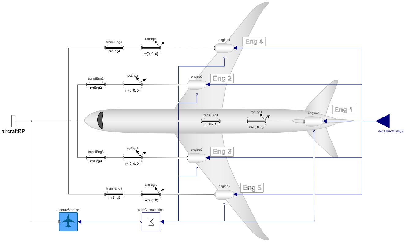
This partial model models a conventional propulsion system with engines mounted on the wings, fuselage or vertical tail, and this extends the PropulsionBase partial model. The complete conventional propulsion system models, namely the TurbofanPropulsion, TurbojetPropulsion, TurbopropPropulsion, PistonPropulsion and ElectricPropulsion models extend this partial model.
In this partial model, the position and orientation of the engine are defined. Additionally, the model for the energy storage is included, and the fuel or energy consumption of all engines is summed here to feed it as an input for the energy storage model.
The constraints of the conventional propulsion models are:
- All engines need to be of same type and model.
- The allowed number of engines is from 0 (for glider) to 4.
- If the number of engines is three, the middle engine is mounted on the vertical tail.
- Only one engine can be mounted on the fuselage centerline.
- Engines cannot be mounted on both the main wing and the fuselage.
- The orientation of the engines is fixed (no thrust vectoring).
The diagram view of this model shows the numbering convention of the engines that is used throughout the library.
Parameters
The number of the engines, if its wing mounted, and their type are defined in the AircraftBase model. Depending on the number of engines and whether the engines are mounted on the main wing or on the fuselage, the editing of the inapplicable parameters will be disabled. For example, for an aircraft with two engines mounted on the main wing, the editing of the parameters xEng, yEngOuter, zTauMid and kappaMid is disabled.
If engines are mounted on the main wing (wingMounted = true), their location along the body x axis is calculated based on the wing geometry, whereas the position along the body y and z axes are defined by the yEngInner / yEngOuter and zTau parameters, respectively. For an aircraft with four engines mounted on the main wing, the zTau parameter refers to the average z coordinate of the inner and outer engines, and the z coordinates of the individual engines are solved based on the main wing dihedral angle. If engines are mounted on the fuselage (wingMounted = false), no calculations are performed for solving for their positions, but they are defined by the xEng, yEngInner / yEngOuter and zTau parameters. If the number of engines is 3, the position of the middle engine (#1) is assumed to be on the vertical tail, and its position on body x axis is solved based on the vertical tail geometry, and its location on the body z axis is defined by the zTauMid parameter. The parameters kappa and kappaMid are used to define the engine thrust line angle, i.e. the orientation of the engines around the body y axis.
A surface roughness height to be used for all engine nacelles can be entered at the Engine Geometry tab. By default, the global surface roughness height defined in the AircraftBase model is used for all nacelles.
The remaining parameters listed in the Propagated Properties tab are propagated from the AircraftBase as the propulsion system is compiled in the propulsion system model and thus they can and should be left unchanged.
Propulsion Mass Properties and Drag
This partial model also has the equations to solve for the total mass, center of mass location, inertia tensor and drag force of the entire propulsion system, which are also used by the AircraftBase model to solve for the mass properties and drag force of the entire aircraft model.
Parameters (44)
| kSkinNac |
Type: Length (m) Description: Nacelle surface roughness height |
|---|---|
| CADshapes |
Type: Boolean Description: true, if external CAD files are used for animation |
| convProp |
Value: true Type: Boolean Description: =true, if conventional propulsion |
| weightEst |
Type: Boolean Description: true, if weight estimation method is used for masses, center of mass location and inertia tensor |
| SrefWing |
Type: Area (m²) Description: Main wing reference area |
| nEng |
Value: 5 Type: Integer Description: Number of engines |
| T0 |
Type: Temperature (K) Description: Temperature at sea-level |
| rho0 |
Type: Density (kg/m³) Description: Air density at sea-level |
| p0 |
Type: Pressure (Pa) Description: Static pressure at sea-level |
| gammaAir |
Type: Real Description: Adiabatic index for air |
| bWing |
Type: Length (m) Description: Main wing span |
| Engine |
Replaceable Class Redeclared as: EngineBase Description: Type of engine model used in the propulsion system |
| engineType |
Type: Integer Description: Type of engine (0 = piston, 1 = turboprop, 2 = turbojet, 3 = turbofan, 4 = electric) |
| wingMounted |
Type: Boolean Description: true, if engines are mounted on the main wing |
| xEng |
Type: Length (m) Description: Fuselage mounted engine / Single engine rear end x-location from fuselage reference point (positive x-axis towards nose) |
| yEngInner |
Value: if nEng == 2 then bWing / 4 else bWing / 3 Type: Length (m) Description: Inner engines y-coordinate w.r.t. fuselage centerline |
| yEngOuter |
Value: bWing / 6 Type: Length (m) Description: Outer engines y-coordinate w.r.t. fuselage centerline |
| zTau |
Value: 0 Type: Length (m) Description: Thrust line z-coordinate w.r.t. fuselage reference point for side (#2-5) engines and single engine |
| zTauMid |
Value: zTau Type: Length (m) Description: Thrust line z-coordinate w.r.t. fuselage reference point for middle (#1) engine |
| kappa |
Value: 0 Type: Angle (rad) Description: Engine thrust line angle for side (#2-5) engines and single engine |
| kappaMid |
Value: 0 Type: Angle (rad) Description: Engine thrust line angle for middle (#1) engine |
| kappaEng1 |
Value: if nEng == 1 then kappa else if nEng == 3 then kappaMid else 0 Type: Angle (rad) Description: Engine thrust line angle for Engine 1 |
| EnergyStorage |
Replaceable Class Redeclared as: EnergyStorageBase Description: Type of energy storage used in the propulsion system |
| tauWing |
Type: Real Description: Ratio of thickness-to-chord ratios at the main wing tip and root |
| xCMdry |
Type: Length (m) Description: Aircraft center of mass x-coordinate w.r.t. fuselage reference point (with total mass for electric aircraft and gliders, positive x-axis towards nose) |
| wFus |
Type: Length (m) Description: Fuselage maximum width |
| hFus |
Type: Length (m) Description: Fuselage maximum height |
| cWingRoot |
Type: Length (m) Description: Main wing root chord (where wing intersects with fuselage) |
| cWingTip |
Type: Length (m) Description: Main wing tip chord |
| tWingRoot |
Type: Length (m) Description: Main wing root thickness |
| tWingTip |
Type: Length (m) Description: Main wing tip thickness |
| xWingRootLE |
Type: Length (m) Description: Main wing root leading edge x-coordinate w.r.t. fuselage reference point (positive x-axis towards nose) |
| zWingRootLE |
Type: Length (m) Description: Main wing root leading edge z-coordinate w.r.t. fuselage reference point (positive z-axis towards ground) |
| lambdaWing |
Type: Angle (rad) Description: Main wing sweep angle at 1/4 chord |
| gammaWing |
Type: Angle (rad) Description: Main wing dihedral angle |
| iWing |
Type: Angle (rad) Description: Main wing incidence angle |
| TRwing |
Type: Real Description: Main wing taper ratio |
| xWingAC |
Type: Length (m) Description: Main wing aerodynamic center from wing leading edge at mean chord (positive x-axis towards nose) |
| yWingAC |
Type: Length (m) Description: Main wing aerodynamic center from fuselage centerline (y-coordinate w.r.t. fuselage centerline of mean chord) |
| lambdaWingLE |
Type: Angle (rad) Description: Main wing leading edge sweep angle |
| lambdaWingHC |
Type: Angle (rad) Description: Main wing half-chord sweep angle |
| bVT |
Type: Length (m) Description: Vertical tail span |
| lVTcm |
Type: Length (m) Description: Vertical tail arm length (from aircraft center of mass to vertical tail 1/4 chord) |
| rEng1 |
Value: if nEng == 3 then {xCMdry - lVTcm - bVT * (3 / 4), 0, zTauMid} else if nEng == 1 then {xEng, 0, zTau} else {0, 0, 0} Type: Length[3] (m) Description: Location of engine 1 rear end w.r.t. fuselage reference point |
Inputs (1)
| flightData |
Type: FlightData Description: Global flight data variables |
|---|
Connectors (2)
| aircraftRP |
Type: Frame_b Description: Connector to aircraft reference point |
|
|---|---|---|
| deltaThrotCmd |
Type: RealInput[nEng] Description: Engine throttle commands |
Components (18)
| flightData |
Type: FlightData Description: Global flight data variables |
|
|---|---|---|
| energyStorage |
Type: EnergyStorage Description: Model for energy storage |
|
| rotEng2 |
Type: FixedRotation Description: Engine 2 thrust line angle (enabled if number of engines = 2 or 3 or 4) |
|
| rotEng3 |
Type: FixedRotation Description: Engine 3 thrust line angle (enabled if number of engines = 2 or 3 or 4) |
|
| rotEng4 |
Type: FixedRotation Description: Engine 4 thrust line angle (enabled if number of engines = 4) |
|
| rotEng5 |
Type: FixedRotation Description: Engine 5 thrust line angle (enabled if number of engines = 4) |
|
| translEng1 |
Type: FixedTranslation Description: Location of engine 1 rear end w.r.t. fuselage reference point |
|
| translEng2 |
Type: FixedTranslation Description: Location of engine 2 rear end w.r.t. fuselage reference point |
|
| translEng3 |
Type: FixedTranslation Description: Location of engine 3 rear end w.r.t. fuselage reference point |
|
| translEng4 |
Type: FixedTranslation Description: Location of engine 4 rear end w.r.t. fuselage reference point |
|
| translEng5 |
Type: FixedTranslation Description: Location of engine 5 rear end w.r.t. fuselage reference point |
|
| engineC |
Type: Engine Description: Model for engine 1 |
|
| engineD |
Type: Engine Description: Type of engine model used in the propulsion system |
|
| engineB |
Type: Engine Description: Type of engine model used in the propulsion system |
|
| engineE |
Type: Engine Description: Type of engine model used in the propulsion system |
|
| engineA |
Type: Engine Description: Type of engine model used in the propulsion system |
|
| sumConsumption |
Type: Sum Description: Summing of fuel / battery energy consumption |
|
| rotEng1 |
Type: FixedRotation Description: Engine 1 thrust line angle |
Used in Components (1)
|
Aircraft.Physical.FixedWing.Interfaces Interface for a complete aircraft model |
Extended by (5)
|
Aircraft.Physical.FixedWing.Parts.Propulsions Electric propulsion (model specific parameters not set) |
|
|
Aircraft.Physical.FixedWing.Parts.Propulsions Piston propulsion (model specific parameters not set) |
|
|
Aircraft.Physical.FixedWing.Parts.Propulsions Turboprop propulsion (model specific parameters not set) |
|
|
Aircraft.Physical.FixedWing.Parts.Propulsions Turbojet propulsion (model specific parameters not set) |
|
|
Aircraft.Physical.FixedWing.Parts.Propulsions Turbofan propulsion (model specific parameters not set) |