WOLFRAM SYSTEM MODELER
AircraftBaseInterface for a complete aircraft model |
|
Diagram
Wolfram Language
In[1]:=
SystemModel["Aircraft.Physical.FixedWing.Interfaces.AircraftBase"]
Out[1]:=
Information
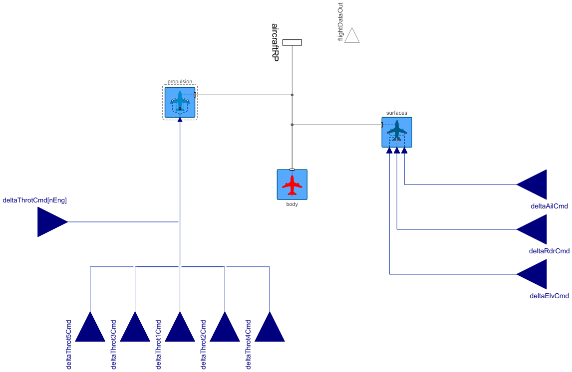
This base model compiles a complete fixed-wing aircraft model with a conventional wing configuration from the propulsion, surface and body components in the Parts package and takes input commands for the control actuator, i.e. commands for throttle position(s) as well as for the ailerons, rudder and elevator deflections. This base model is extended by the complete aircraft models found in the Aircraft.Physical.FixedWing package and can also be extended by the user's own fixed-wing aircraft designs with conventional wing configuration.
Parameters
Due to many couplings between the characteristics of different components of the aircraft, most of the aircraft parameters are declared on this top-level aircraft model instead of declaring them lower at the component models. The parameters declared here are propagated down to the components where they are needed.
General Tab
The most important parameters are declared in this tab, divided in their respective groups of Mass, Propulsion, Main Wing Geometry, Horizontal Tail Geometry, Vertical Tail Geometry, Aerodynamics and Initialization. The component is built in a way where the most detailed parameters can be estimated based on sizing correlations for early stages of aircraft design. If more information is available on the model, they can be overwritten and thus the correlations become bypassed. More detailed propulsion parameters are defined in their respective propulsion type (TurbofanPropulsion, TurbojetPropulsion, TurbopropPropulsion, PistonPropulsion or ElectricPropulsion).
Mass and Inertia Tab
In this tab, the dry center of gravity and the airplane's complete moments of inertia are declared. which all remain constant during a simulation. The mass of the initial fuel is defined separately with the initialMfuel parameter in the General Tab, and the consequent center of mass location and variable inertia tensor of the fuel system are estimated in the TankSystem component, regardless of whether the weight estimation method is used or not.
The last group in this tab, namely the Design Parameters for Weight Estimation, declares whether the weight estimation method is used to estimate the mass properties of the aircraft component by component or if the known mass properties of the entire aircraft are entered directly. Depending on its value, the editing of the relevant mass property or design variable parameters is enabled. When the weight estimation method is used, the initial fuel mass is adjusted as a fraction of the estimated maximum fuel capacity in the Fuel System parameter tab of the propulsion component.
Geometry Tab
In this parameter tab, more detailed positioning of the wing, horizontal and vertical tail, and fuselage are declared. Initially, the values are estimated using correlation rules. The fuselage reference point is defined at the half-length of all given maximum fuselage dimensions, as shown in Figure 3 in Aircraft.Physical.FixedWing.Introduction.
Aerodynamics Tab
The required aerodynamic properties to be entered for the aircraft model are the properties of the two-dimensional airfoils used in the main wing, horizontal tail and vertical tail and the surface roughness height on different surfaces. By default, the given surface roughness height for the entire aircraft (kSkinAC) is propagated to be used on the surfaces of all components, including the surface of the nacelles in the turbofan, turbojet and turboprop engines.
The derivation of the lift and drag coefficients of the wings and the fuselage from the given Aerodynamic Properties and Geometry parameters is described in the documentation for WingBody, HorizontalTail and VerticalTail components, and the derivation of the drag coefficients of the nacelles in the turbofan, turbojet and turboprop engines is described in their respective documentation.
Control Surfaces Tab
The maximum control surface deflections given here are propagated to be used in the limiters in the Ailerons, HorizontalTail and VerticalTail components, as well as effectiveness coefficients estimations.
Initialization Tab
The main initialization parameters (i.e. initialAltitude & initialVelocity) are declared in the General Tab. Here, more detailed information regarding initialization can be introduced, namely initial position, orientation and translational and rotational velocities are entered here. The initialization for the translational velocity is performed in this model from the Start Flight Conditions group, whereas the initialization for the position, orientation and angular velocity is performed in the Body model.
By default, the Modelica Standard Library FixedShape primitives are used to visualize different components with simple box and cylinder shapes with the dimensions given in the Geometry parameters and by estimating them for certain components. However, if a CAD model of the complete aircraft model exists as an .obj file, it can be used by setting CADshapes as true and entering the path of the .obj file to the CADpath field. This automatically disables the default animation in every component. The rotation and translation between the CAD object origin and the fuselage reference point can be entered into the translCADshape in the Body model.
Derived Properties
This tab is intentionally blank at the aircaft model level since it includes equations with all the parameters preivously introduced, which will be propagated into lower levels of the model.
Variables
The variables of the complete aircraft that are solved for in this model by fetching the required variables from the subcomponents include:
- Flight data variables, which are to be stored in the FlightData record and outputted through the FlightDataOut connector
- Drag coefficient and the lift-to-drag ratio (CDac and LDratio; aircraft lift coefficient is solved in the surfaces component)
- Kinetic energy (Ekin), potential energy (Epot), rotational energy (Erot) and their sum, the total energy (Etot)
- Total net power output (Pnet, derivative of total energy) and energy dissipation rate (Pdiss, total net power output subtracted by gross power used by engines)
- Mass properties
As the mass properties of a rigid multi-body system are not automatically solved, first the center of mass location for the entire aircraft including the contribution from the variable fuel mass (xCM, yCM, zCM) is calculated. Then, the moments of inertia around this center of mass (Ixx, Iyy, Izz) are solved by using the parallel axis theorem, and the total products of inertia (Ixy, Ixz, Iyz) are solved by summing the products of component masses and their coordinates with respect to the solved aircraft center of mass.
This method, however, is a minor simplification, as it considers the local frames of the main wing and horizontal tail surfaces to be parallel with the fuselage reference plane. In fact, the moments of inertia of the main wing and horizontal tail are solved in a frame parallel to their surfaces by considering the rotations around their incidence and dihedral angles.
Connectors
This model contains real inputs for the control actuators, a frame connected to the fuselage reference point (aircraftRP), and a FlightDataOut connector for forwarding the variables of the flight data as feedback to the autopilots. The aircraftRP frame can be used, for example, to create physical connection to other aircraft, as is done in the GliderTow example. For more detailed information on the thrust connectors, refer to Aircraft.GettingStarted.
References
[1] Erä-Esko, N. (2022). "Development and Use of System Modeler 6DOF Flight Mechanics Model in Aircraft Conceptual Design."
Available at: modelica://Aircraft/Resources/Documents/EraeEskoThesis.pdf.
Parameters (146)
| mDry |
Type: Mass (kg) Description: Aircraft dry mass (total mass for electric aircraft and gliders) |
|---|---|
| initialMfuel |
Value: 0.2 * mDry Type: Mass (kg) Description: Initial fuel mass |
| xCMdry |
Type: Length (m) Description: Aircraft center of mass x coordinate w.r.t. fuselage reference point (with total mass for electric aircraft and gliders, positive x axis toward nose) |
| yCMdry |
Value: 0 Type: Length (m) Description: Aircraft center of mass y coordinate w.r.t. fuselage reference point (with total mass for electric aircraft and gliders, positive y axis toward right) |
| zCMdry |
Value: 0 Type: Length (m) Description: Aircraft center of mass z coordinate w.r.t. fuselage reference point (with total mass for electric aircraft and gliders, positive z axis toward ground) |
| IxxDry |
Value: 2 * (mDry + initialMfuel) * defaultInertiaFactor Type: MomentOfInertia (kg⋅m²) Description: Aircraft dry moment of inertia about x axis |
| IyyDry |
Value: 2 * (mDry + initialMfuel) * defaultInertiaFactor Type: MomentOfInertia (kg⋅m²) Description: Aircraft dry moment of inertia about y axis |
| IzzDry |
Value: 3.62 * (mDry + initialMfuel) * defaultInertiaFactor Type: MomentOfInertia (kg⋅m²) Description: Aircraft dry moment of inertia about z axis |
| IxyDry |
Value: 0 Type: MomentOfInertia (kg⋅m²) Description: Aircraft xy product of dry moment of inertia |
| IxzDry |
Value: 0 Type: MomentOfInertia (kg⋅m²) Description: Aircraft xz product of dry moment of inertia |
| IyzDry |
Value: 0 Type: MomentOfInertia (kg⋅m²) Description: Aircraft yz product of dry moment of inertia |
| MTOMdes |
Type: Mass (kg) Description: Design maximum takeoff mass |
| nPax |
Type: Integer Description: Design number of passengers |
| mPLdes |
Type: Mass (kg) Description: Design payload mass |
| machDes |
Type: Real Description: Design Mach number |
| compMat |
Type: Boolean Description: true, if composite materials are used in structures |
| qMax |
Type: Pressure (Pa) Description: Maximum dynamic pressure |
| nMax |
Type: Real Description: Maximum load factor |
| nEng |
Type: Integer Description: Number of engines |
| wingMounted |
Type: Boolean Description: true, if engines are mounted on the main wing |
| engineType |
Type: Integer Description: Type of engine (0 = piston, 1 = turboprop, 2 = turbojet, 3 = turbofan, 4 = electric) |
| bWing |
Type: Length (m) Description: Main wing span |
| cWingRoot |
Type: Length (m) Description: Main wing root chord (where wing intersects with fuselage) |
| cWingTip |
Type: Length (m) Description: Main wing tip chord |
| tWingRoot |
Value: 0.13 * cWingMean Type: Length (m) Description: Main wing root thickness |
| tWingTip |
Value: tWingRoot Type: Length (m) Description: Main wing tip thickness |
| xWingRootLE |
Value: 0.3 * cWingMean Type: Length (m) Description: Main wing root leading edge x coordinate w.r.t. fuselage reference point (positive x axis toward nose) |
| zWingRootLE |
Value: 0 Type: Length (m) Description: Main wing root leading edge z coordinate w.r.t. fuselage reference point (positive z axis toward ground) |
| lambdaWing |
Value: 0 Type: Angle (rad) Description: Main wing sweep angle at 1/4 chord |
| gammaWing |
Value: 0 Type: Angle (rad) Description: Main wing dihedral angle |
| iWing |
Value: 0 Type: Angle (rad) Description: Main wing incidence angle |
| bHT |
Type: Length (m) Description: Horizontal tail span |
| cHTroot |
Type: Length (m) Description: Horizontal tail root chord |
| cHTtip |
Type: Length (m) Description: Horizontal tail tip chord |
| tHTroot |
Value: 0.09 * cHTmean Type: Length (m) Description: Horizontal tail root thickness |
| tHTtip |
Value: tHTroot Type: Length (m) Description: Horizontal tail tip thickness |
| xHTrootLE |
Type: Length (m) Description: Horizontal tail root leading edge x coordinate w.r.t. fuselage reference point (positive x axis toward nose) |
| zHTrootLE |
Value: 0 Type: Length (m) Description: Horizontal tail root leading edge z coordinate w.r.t. fuselage reference point (positive z axis toward ground) |
| lambdaHT |
Value: 0 Type: Angle (rad) Description: Horizontal tail sweep angle at 1/4 chord |
| iHT |
Value: 0 Type: Angle (rad) Description: Horizontal tail incidence angle |
| bVT |
Type: Length (m) Description: Vertical tail span |
| cVTroot |
Type: Length (m) Description: Vertical tail root chord |
| cVTtip |
Type: Length (m) Description: Vertical tail tip chord |
| tVTroot |
Value: 0.09 * cVTmean Type: Length (m) Description: Vertical tail root thickness |
| tVTtip |
Value: tVTroot Type: Length (m) Description: Vertical tail tip thickness |
| xVTrootLE |
Value: xHTrootLE Type: Length (m) Description: Vertical tail root leading edge x coordinate w.r.t. fuselage reference point (positive x axis toward nose) |
| zVTroot |
Value: 0 Type: Length (m) Description: Vertical tail root z coordinate w.r.t fuselage reference point |
| lambdaVT |
Value: 0 Type: Angle (rad) Description: Vertical tail sweep angle at 1/4 chord |
| lFus |
Value: 0.7 * bWing Type: Length (m) Description: Fuselage length |
| wFus |
Value: 0.2 * lFus Type: Length (m) Description: Fuselage maximum width |
| hFus |
Value: wFus Type: Length (m) Description: Fuselage maximum height |
| dFusHT |
Value: 0.25 * wFus Type: Length (m) Description: Fuselage diameter at horizontal tail 1/4 chord |
| kSkinAC |
Value: 6.35e-06 Type: Length (m) Description: Surface roughness height (same value to be used for all components) |
| kSkinWing |
Value: kSkinAC Type: Length (m) Description: Main wing surface roughness height |
| ClAlphaWing2D |
Value: 2 * Modelica.Constants.pi Type: CurveSlope (rad⁻¹) Description: Change in the section lift coefficient of the main wing airfoil (2D) due to alpha |
| alpha0Wing2D |
Value: 0 Type: Angle (rad) Description: Zero-lift angle of attack of the main wing airfoil (2D) |
| ClMaxWing2D |
Value: 1.2 Type: Real Description: Maximum section lift coefficient of the main wing airfoil (2D) |
| kSkinHT |
Value: kSkinAC Type: Length (m) Description: Horizontal tail surface roughness height |
| ClAlphaHT2D |
Value: 2 * Modelica.Constants.pi Type: CurveSlope (rad⁻¹) Description: Change in the section lift coefficient of the horizontal tail airfoil (2D) due to alpha |
| alpha0HT2D |
Value: 0 Type: Angle (rad) Description: Zero-lift angle of attack of the horizontal tail airfoil (2D) |
| ClMaxHT2D |
Value: 1.2 Type: Real Description: Maximum section lift coefficient of the horizontal tail airfoil (2D) |
| kSkinVT |
Value: kSkinAC Type: Length (m) Description: Vertical tail surface roughness height |
| ClAlphaVT2D |
Value: 2 * Modelica.Constants.pi Type: CurveSlope (rad⁻¹) Description: Change in the section lift coefficient of the vertical tail airfoil (2D) due to alpha |
| kSkinFus |
Value: kSkinAC Type: Length (m) Description: Fuselage surface roughness height |
| deltaElvMax |
Value: 0.392699081698724 Type: Angle (rad) Description: Maximum elevator deflection |
| deltaAilMax |
Value: 0.392699081698724 Type: Angle (rad) Description: Maximum aileron deflection |
| deltaRdrMax |
Value: 0.785398163397448 Type: Angle (rad) Description: Maximum rudder deflection |
| cAil |
Value: 0.125 * cWingMean Type: Length (m) Description: Aileron average chord |
| yAilRoot |
Value: 0 Type: Length (m) Description: Aileron root y-coordinate w.r.t. fuselage centerline |
| yAilTip |
Value: bWing / 2 Type: Length (m) Description: Aileron tip y-coordinate w.r.t. fuselage centerline |
| Selv |
Value: 0.25 * SrefHT Type: Area (m²) Description: Elevator area |
| Srdr |
Value: 0.025 * SrefWing Type: Area (m²) Description: Rudder area |
| sigmaBeta |
Value: max(3.06 * (SrefVT / SrefWing) / (1 + cos(lambdaWing)) + 0.4 * (-tan(gammaWing) * (yWingAC - wFus / 2) + zWingRootLE) / wFus + 0.009 * (bWing ^ 2 / SrefWing) - 0.276, 0) Type: Real Description: Change in sidewash due to beta |
| rACcm |
Value: if weightEst then {xWingRootLE - lambdaWingLE * (yWingAC - wFus / 2) - 0.15 * cWingMean, 0, 0} else {xCMdry, yCMdry, zCMdry} Type: Length[3] (m) Description: Aircraft dry center of mass w.r.t. fuselage reference point (estimated to be at 15% of MAC if weight estimation method is used) |
| Cfus |
Value: Modelica.Constants.pi * (3 * (hFus / 2 + wFus / 2) - sqrt(10 * hFus / 2 * wFus / 2 + 3 * ((hFus / 2) ^ 2 + (wFus / 2) ^ 2))) Type: Length (m) Description: Fuselage circumference |
| SwetFus |
Value: Cfus * lFus * (1 - 2 / (lFus / (Cfus / Modelica.Constants.pi))) ^ (2 / 3) * (1 + 1 / (lFus / (Cfus / Modelica.Constants.pi)) ^ 2) Type: Area (m²) Description: Fuselage wetted area |
| FFfus |
Value: 1 + 0.0025 * (lFus / hFus) + 60 * (hFus / lFus) ^ 3 Type: Real Description: Fuselage form factor |
| CDmaxFus |
Value: 0.8 * lFus * hFus / SrefWing Type: Real Description: Maximum drag coefficient of the fuselage |
| nSeatAbs |
Value: if nPax > 180 then floor(0.9 * wFus / seatWidth) - 1 else floor(0.9 * wFus / seatWidth) Type: Real Description: Number of seats abreast |
| cWingMean |
Value: 2 / 3 * cWingRoot * ((1 + TRwing + TRwing ^ 2) / (1 + TRwing)) Type: Length (m) Description: Main wing mean chord length |
| xWingAC |
Value: -0.25 * cWingMean Type: Length (m) Description: Main wing aerodynamic center from wing leading edge at mean chord (positive x-axis towards nose) |
| yWingAC |
Value: bWing / 6 * (cWingRoot + 2 * cWingTip) / (cWingRoot + cWingTip) Type: Length (m) Description: Main wing aerodynamic center from fuselage centerline (y-coordinate w.r.t. fuselage centerline of mean chord) |
| SwetWing |
Value: 2 * (SrefWing / cos(gammaWing) - cWingRoot * wFus) * (1 + 0.25 * (tWingRoot / cWingRoot) * (1 + tWingTip / cWingTip / (tWingRoot / cWingRoot) * TRwing) / (1 + TRwing)) Type: Area (m²) Description: Main wing wetted area |
| CLmaxWing3D |
Value: 0.9 * ClMaxWing2D * cos(lambdaWing) Type: Real Description: Maximum lift coefficient of the main wing (3D) |
| CDmaxWing3D |
Value: 1.98 - 0.81 * (1 - Modelica.Constants.e ^ (-20 / ARwing)) Type: Real Description: Maximum drag coefficient of the main wing (3D) |
| FFwing |
Value: 0.421 * (2 + 4 * tWingMean / cWingMean + 240 * (tWingMean / cWingMean) ^ 4) Type: Real Description: Main wing form factor |
| sdWing |
Value: 0.9998 + 0.0421 * (wFus / bWing) - 2.6286 * (wFus / bWing) ^ 2 + 2 * (wFus / bWing) ^ 3 Type: Real Description: Fuselage drag factor for main wing |
| kdWing |
Value: -3.333 * 10 ^ (-4) * lambdaWing ^ 2 + 6.667 * 10 ^ (-5) * lambdaWing + 0.38 Type: Real Description: Empirical constant for Oswald efficiency factor for main wing |
| kCnDeltaAil |
Value: -0.350894 - 0.066355 * (yAilRoot / (bWing / 2)) ^ 4.15179 + 0.029308 * (bWing ^ 2 / SrefWing) Type: Real Description: Empirical factor for the yaw moment derivative due to ailerons |
| tauAil |
Value: 1.129 * (Sail / SrefWing) ^ 0.4044 - 0.1772 Type: Real Description: Aileron effectiveness coefficient |
| SrefHT |
Value: (cHTroot + cHTtip) * (bHT - dFusHT) / 2 + cHTroot * dFusHT Type: Area (m²) Description: Horizontal tail reference area |
| cHTmean |
Value: 2 / 3 * cHTroot * (1 + TRht + TRht ^ 2) / (1 + TRht) Type: Length (m) Description: Horizontal tail mean chord |
| SwetHT |
Value: 2 * (SrefHT - cHTroot * dFusHT) * (1 + 0.25 * (tHTroot / cHTroot) * (1 + tHTtip / cHTtip / (tHTroot / cHTroot) * TRht) / (1 + TRht)) Type: Area (m²) Description: Horizontal tail wetted area |
| CLmaxHT3D |
Value: 0.9 * ClMaxHT2D * cos(lambdaHT) Type: Real Description: Maximum lift coefficient of the horizontal tail (3D) |
| CDmaxHT3D |
Value: 1.98 - 0.81 * (1 - Modelica.Constants.e ^ (-20 / ARht)) Type: Real Description: Maximum drag coefficient of the horizontal tail (3D)*(SrefHT/SrefWing) |
| FFht |
Value: 1 + 0.1 * (1 - 0.893 * abs(zHTrootLE / hFus)) * (2 + 4 * tHTmean / cHTmean + 240 * (tHTmean / cHTmean) ^ 4) Type: Real Description: Horizontal tail form factor |
| sdHT |
Value: 0.9998 + 0.0421 * (dFusHT / bHT) - 2.6286 * (dFusHT / bHT) ^ 2 + 2 * (dFusHT / bHT) ^ 3 Type: Real Description: Fuselage drag factor for horizontal tail |
| kdHT |
Value: -3.333 * 10 ^ (-4) * lambdaHT ^ 2 + 6.667 * 10 ^ (-5) * lambdaHT + 0.38 Type: Real Description: Empirical constant for Oswald efficiency factor for horizontal tail |
| tauElv |
Value: 1.129 * (Selv / SrefHT) ^ 0.4044 - 0.1772 Type: Real Description: Elevator effectiveness coefficient |
| cVTmean |
Value: 2 / 3 * cVTroot * (1 + TRvt + TRvt ^ 2) / (1 + TRvt) Type: Length (m) Description: Vertical tail mean chord |
| SwetVT |
Value: 2 * SrefVT * (1 + 0.25 * (tVTroot / cVTroot) * (1 + tVTtip / cVTtip / (tVTroot / cVTroot) * TRvt) / (1 + TRvt)) Type: Area (m²) Description: Vertical tail wetted area |
| FFvt |
Value: 0.5 * (2 + 4 * tVTmean / cVTmean + 240 * (tVTmean / cVTmean) ^ 4) Type: Real Description: Vertical tail form factor |
| sdVT |
Value: 0.9998 Type: Real Description: Fuselage drag factor for vertical tail |
| kdVT |
Value: -3.333 * 10 ^ (-4) * lambdaVT ^ 2 + 6.667 * 10 ^ (-5) * lambdaVT + 0.38 Type: Real Description: Empirical constant for Oswald efficiency factor for vertical tail |
| tauRdr |
Value: 1.129 * (Srdr / SrefVT) ^ 0.4044 - 0.1772 Type: Real Description: Rudder effectiveness coefficient |
| initialAltitude |
Type: Altitude (m) Description: Initial altitude |
| initialLatPosition |
Value: {0, 0} Type: Position[2] (m) Description: Initial lateral position of the aircraft (x and y coordinates in world frame) |
| initialVelocity |
Type: Velocity (m/s) Description: Initial velocity |
| initialTrack |
Value: 0 Type: Angle (rad) Description: Initial track angle |
| initialGamma |
Value: 0 Type: Angle (rad) Description: Initial flight path angle |
| initialPhi |
Value: 0 Type: Angle (rad) Description: Initial roll angle |
| initialTheta |
Value: 0 Type: Angle (rad) Description: Initial pitch angle |
| initialPsi |
Value: 0 Type: Angle (rad) Description: Initial yaw angle (heading) |
| initialAngularVelocity |
Value: {0, 0, 0} Type: AngularVelocity[3] (rad/s) Description: Initial {roll [p], pitch [q], yaw [r]} |
| CADshapes |
Type: Boolean Description: True, if external CAD files are used for animation |
| CADpath |
Value: "modelica://Aircraft/Resources/CAD/PathName.obj" Type: String Description: Path for CAD file |
| propulsion |
Replaceable Component Type: ConventionalPropulsion Description: Propulsion model |
| SrefWing |
Value: (cWingRoot + cWingTip) * (bWing - wFus) / 2 + cWingRoot * wFus Type: Area (m²) Description: Main wing reference area |
| SrefVT |
Value: (cVTroot + cVTtip) / 2 * bVT Type: Area (m²) Description: Vertical tail reference area |
| weightEst |
Value: false Type: Boolean Description: True, if weight estimation method is used for masses, center of mass location and inertia tensor |
| ARwing |
Value: bWing ^ 2 / SrefWing Type: Real Description: Main wing aspect ratio |
| TRwing |
Value: cWingTip / cWingRoot Type: Real Description: Main wing taper ratio |
| tWingMean |
Value: (yWingAC - wFus / 2) * (tWingTip - tWingRoot) / (bWing / 2 - wFus / 2) + tWingRoot Type: Length (m) Description: Main wing mean thickness |
| lambdaWingLE |
Value: atan((cWingRoot / 4 - cWingTip / 4 + tan(lambdaWing) * bWing / 2) / (bWing / 2)) Type: Angle (rad) Description: Main wing leading edge sweep angle |
| lambdaWingHC |
Value: atan((cWingTip / 4 - cWingRoot / 4 + tan(lambdaWing) * bWing / 2) / (bWing / 2)) Type: Angle (rad) Description: Main wing half-chord sweep angle |
| lambdaWingTE |
Value: atan((lambdaWingLE * ((bWing - wFus) / 2) + cWingTip - cWingRoot) / ((bWing - wFus) / 2)) Type: Angle (rad) Description: Main wing trailing edge sweep angle (at ailerons location) |
| ARht |
Value: bHT ^ 2 / SrefHT Type: Real Description: Aspect ratio of horizontal tail |
| TRht |
Value: cHTtip / cHTroot Type: Real Description: Taper ratio of horizontal tail |
| tHTmean |
Value: bHT / 2 * (1 + 2 * TRht) / (3 + 3 * TRht) * (tHTtip - tHTroot) / (bHT / 2 - dFusHT / 2) + tHTroot Type: Length (m) Description: Horizontal tail mean thickness |
| lHTcm |
Value: abs(xHTrootLE - xCMdry - tan(lambdaHTle) * (bHT / 2 - dFusHT / 2) * (1 + 2 * TRht) / (3 + 3 * TRht) - 0.25 * cHTmean) Type: Length (m) Description: Horizontal tail arm length (from aircraft center of mass to horizontal tail 1/4 chord) |
| lHTwingAC |
Value: abs(xHTrootLE - (xWingRootLE - lambdaWingLE * (yWingAC - wFus / 2))) + tan(lambdaHTle) * (bHT / 2 - dFusHT / 2) * (1 + 2 * TRht) / (3 + 3 * TRht) + 0.25 * cHTmean - abs(xWingAC) Type: Length (m) Description: Horizontal tail arm length (from wing aerodynamic center to horizontal tail 1/4 chord) |
| vHT |
Value: SrefHT / SrefWing * (lHTcm / cWingMean) Type: Real Description: Horizontal tail volume coefficient |
| lambdaHTle |
Value: atan((cHTroot / 4 - cHTtip / 4 + tan(lambdaHT) * bHT / 2) / (bHT / 2)) Type: Angle (rad) Description: Horizontal tail leading edge sweep angle |
| ARvt |
Value: bVT ^ 2 / SrefVT Type: Real Description: Aspect ratio of vertical tail |
| TRvt |
Value: cVTtip / cVTroot Type: Real Description: Taper ratio of vertical tail |
| tVTmean |
Value: bVT * (1 + 2 * TRvt) / (3 + 3 * TRvt) * (tVTtip - tVTroot) / bVT + tVTroot Type: Length (m) Description: Vertical tail mean thickness |
| lVTcm |
Value: abs(xVTrootLE - xCMdry - tan(lambdaVTle) * bVT * (1 + 2 * TRvt) / (3 + 3 * TRvt) - 0.25 * cVTmean) Type: Length (m) Description: Vertical tail arm length (from aircraft center of mass to vertical tail 1/4 chord) |
| lVTwingAC |
Value: abs(xVTrootLE - (xWingRootLE - lambdaWingLE * (yWingAC - wFus / 2))) + tan(lambdaVTle) * bVT * (1 + 2 * TRvt) / (3 + 3 * TRvt) + 0.25 * cVTmean - abs(xWingAC) Type: Length (m) Description: Vertical tail arm length (from wing aerodynamic center to vertical tail aerodynamic center) |
| zVTac |
Value: zVTroot - bVT * (1 + 2 * TRvt) / (3 + 3 * TRvt) Type: Length (m) Description: Vertical tail center of pressure z-coordinate w.r.t. fuselage reference point |
| vVT |
Value: SrefVT / SrefWing * (lVTcm / bWing) Type: Real Description: Vertical tail volume coefficient |
| lambdaVTle |
Value: atan((tan(lambdaVT) * bVT - cVTtip / 4 + cVTroot / 4) / bVT) Type: Angle (rad) Description: Vertical tail leading edge sweep angle |
| T0 |
Value: atmos.T0 Type: Temperature (K) Description: Temperature at sea level |
| rho0 |
Value: atmos.mAir * p0 / (atmos.R0 * T0) Type: Density (kg/m³) Description: Air density at sea level |
| a0 |
Value: sqrt(atmos.gammaAir * atmos.R0 / atmos.mAir * T0) Type: Velocity (m/s) Description: Speed of sound at sea level |
| gammaAir |
Value: atmos.gammaAir Type: Real Description: Adiabatic index for air |
| tauWing |
Value: tWingTip / cWingTip / (tWingRoot / cWingRoot) Type: Real Description: Ratio of thickness-to-chord ratios at the main wing tip and root |
Outputs (1)
| xEtot |
Type: Energy (J) Description: State of aircraft total energy |
|---|
Connectors (6)
| deltaAilCmd |
Type: RealInput Description: Ailerons deflection command |
|
|---|---|---|
| deltaElvCmd |
Type: RealInput Description: Elevator deflection command |
|
| deltaRdrCmd |
Type: RealInput Description: Rudder deflection command |
|
| aircraftRP |
Type: Frame_b Description: Connector to aircraft reference point |
|
| flightDataOut |
Type: FlightDataOut Description: Flight data output |
|
| deltaThrotCmd |
Type: RealInput[nEng] Description: Engine throttle commands when custom propulsion is used |
Components (5)
| atmos |
Type: AtmosphericProperties Description: Property parameters for the U.S. Standard Atmosphere |
|
|---|---|---|
| flightData |
Type: FlightData Description: Global flight data variables (measured at the aircraft center of mass location) |
|
| body |
Type: Body Description: Model for the mass properties of entire aircraft or only fuselage, landing gear and payload if weight estimation method is used |
|
| propulsion |
Type: ConventionalPropulsion Description: Propulsion model |
|
| controlSurfaces |
Type: Conventional Description: Model of system of surfaces in conventional wing configuration |
Extended by (8)
|
Aircraft.Physical.FixedWing Narrow-body turbofan airliner: Hawker Siddeley HS-121 Trident 3B |
|
|
Aircraft.Physical.FixedWing High-speed turboprop airliner: Saab 2000 |
|
|
Aircraft.Physical.FixedWing Light-sport electric aircraft: Pipistrel Alpha Electro |
|
|
Aircraft.Physical.FixedWing Model of a general aviation aircraft |
|
|
Aircraft.Physical.FixedWing Model of a general aviation aircraft |
|
|
Aircraft.Physical.FixedWing Mid-wing glider: Schweizer SGS 1-36 |
|
|
Aircraft.Physical.FixedWing Narrow-body turbojet airliner: Douglas DC-8-20 |
|
|
Aircraft.Physical.FixedWing Narrow-body turbofan airliner: Boeing 737-800 |