WOLFRAM SYSTEM MODELER
TurbopropEngineTurboprop engine: unparameterized |
|
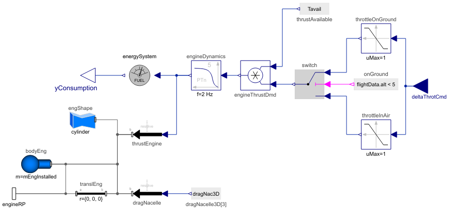
Diagram
Wolfram Language
In[1]:=
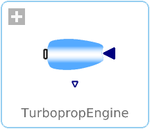
SystemModel["Aircraft.Physical.FixedWing.Parts.Propulsions.Engines.TurbopropEngines.TurbopropEngine"]
Out[1]:=
Information
This turboprop engine model extends the EngineBase model and models the thrust, drag and mass properties (if weight estimation method is used) of a turboprop engine.
Parameters
The required parameters for the turboprop engine model are listed in the Propulsion tab, as shown in Figure 1.
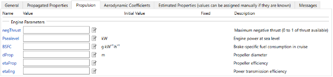
Figure 1: Required input parameters for turboprop engine model.
Should the value of any of the estimated properties listed in the Estimated Properties parameter tab be known (such as engine mass, nacelle length or diameter), the equations can be bypassed by entering the known value directly to the respective parameter input field. Similarly, if the surface roughness height of the nacelles is known, its value can be entered inside the Aerodynamic Coefficients tab. Otherwise its value is propagated from the global surface roughness height declared in AircraftBase.
The remaining parameters listed in the Propagated Properties tab are propagated from the AircraftBase as the propulsion system is compiled in TurbopropPropulsion, and thus they can and should be left unchanged.
Thrust Available
The thrust available (Tavail) for turboprop engines is solved through dividing the power available (Pavail) by the total velocity (vtot), and the factors for representing the propeller (ηprop) and power transmission efficiencies (ηmech) are also added, thus
![]() .
.
For solving the power available, a relation presented by Anderson [1] is used
![]() ,
,
where P0 is the engine power at sea level, ρalt is air density at flight altitude and ρ0 is air density at sea level.
Fuel Consumption
The parameter for brake-specific fuel consumption (BSFC) is propagated to the energySystem component, where fuel consumption calculations are performed.
Drag Due to Nacelle
For solving the parasite drag coefficient (CD,0,nac) of different components in the aircraft, including the engine nacelles, the component buildup method presented by Raymer [2] is used, defined as
![]() ,
,
where the nacelle form factor (FFnac) and the nacelle wetted area (Swet,nac) are functions of the estimated (or entered, if known) values of nacelle diameter and length. The nacelle dimensions are estimated through empirical relationships as a function of the engine static thrust. However, the performance of a turboprop engine is described by its power at sea level rather than the static thrust. To derive a static thrust value for turboprop engine, a relation presented by Sforza [3] is used
![]() ,
,
where dprop is the propeller diameter. Thus, the more powerful the engine and the larger the propeller, the larger the parasite drag coefficient.
The skin friction coefficient (Cf,nac) is a function of the nacelle surface roughness height, Mach number and the Reynolds number for the flow over the nacelle, and thus the air compressibility effects are included in the drag calculations. The complete derivation of the CD,0,nac can be found in section 3.3.1 in Reference [4].
The magnitude of the drag force itself (Dnac) is the parasite drag coefficient times the dynamic pressure (q) times the main wing reference area (Sref,w)
![]() .
.
In this model, only the parasite drag of the nacelle is considered, and thus the drag force generated by the nacelle is invariable with the angle of attack. Consequently, the lift generated by the nacelle due to angle of attack is also omitted.
Mass Properties
If the weight estimation method is used and no mass properties are entered by the user, the engine mass is solved by using the empirical relationship based on the calculated Tstatic value, as presented by Isikveren [5].
The engine moments of inertia are estimated as if the engine were a solid cylinder with its estimated length and diameter. Hence, the center of mass of the engine is also estimated to be at the geometric center of this cylinder.
The full derivations of the estimated engine mass and moments of inertia are also shown in Reference [4] in sections 3.4.4 and 3.6.1, respectively.
References
[1] Anderson, J. D. (2012). Aircraft Performance and Design. Mcgraw-Hill Higher.
[2] Raymer, D. P. (1992). Aircraft Design: A Conceptual Approach, 2nd Ed. American Institute of Aeronautics and Astronautics.
[3] Sforza, P. M. (2017). Theory of Aerospace Propulsion, 2nd Ed. Elsevier.
[4] Erä-Esko, N. (2022). "Development and Use of System Modeler 6DOF Flight Mechanics Model in Aircraft Conceptual Design."
Available at: modelica://Aircraft/Resources/Documents/EraeEskoThesis.pdf.
Parameters (26)
| weightEst |
Type: Boolean Description: true, if weight estimation method is used for masses, center of mass location and inertia tensor |
|---|---|
| bWing |
Type: Length (m) Description: Main wing span |
| SrefWing |
Type: Area (m²) Description: Main wing reference area |
| CADshapes |
Type: Boolean Description: true, if external CAD files are used for animation |
| negThrust |
Type: Real Description: Maximum negative thrust (0 to 1 of thrust available) |
| EnergySystem |
Replaceable Class Redeclared as: FuelSystemBrakeSpecific Description: Consumed fuel of piston and turboprop engines |
| rho0 |
Type: Density (kg/m³) Description: Air density at sea-level |
| Psealevel |
Type: Power (W) Description: Engine power at sea level |
| BSFC |
Type: BrakeSpecificFuelConsumption (kg⋅W⁻¹⋅s⁻¹) Description: Brake-specific fuel consumption in cruise |
| dProp |
Type: Length (m) Description: Propeller diameter |
| etaProp |
Type: Real Description: Propeller efficiency |
| etaEng |
Type: Real Description: Power transmission efficiency |
| kSkinNac |
Type: Length (m) Description: Nacelle surface roughness height |
| mNac |
Value: 0.345 * 0.47 * mEngDry Type: Mass (kg) Description: Nacelle mass |
| mProp |
Value: 6.13 * (Tstatic * N2kg) / 1000 Type: Mass (kg) Description: Propeller mass |
| mEngDry |
Value: 0.0117 * 1.2 * Tstatic ^ 1.0572 Type: Mass (kg) Description: Engine dry mass |
| mEngInstalled |
Value: mEngDry + mNac + mProp Type: Mass (kg) Description: Installed engine mass |
| xEngCM |
Value: lNac / 2 Type: Length (m) Description: Engine center of mass x-coordinate w.r.t. engine rear end |
| IxxEng |
Value: mEngInstalled * (dNac / 2) ^ 2 / 2 Type: MomentOfInertia (kg⋅m²) Description: Engine roll moment of inertia |
| IyyEng |
Value: mEngInstalled * (dNac / 2) ^ 2 / 4 + mEngInstalled * lNac ^ 2 / 12 Type: MomentOfInertia (kg⋅m²) Description: Engine pitch moment of inertia |
| IzzEng |
Value: mEngInstalled * (dNac / 2) ^ 2 / 4 + mEngInstalled * lNac ^ 2 / 12 Type: MomentOfInertia (kg⋅m²) Description: Engine yaw moment of inertia |
| dNac |
Value: 4 * (0.0625 + 1 / (4 * sqrt(2)) * max(1.730 * log(max(Tstatic / 1000, 1)) - Modelica.Constants.pi, 0) ^ 0.5) Type: Length (m) Description: Nacelle diameter |
| lNac |
Value: 5 * (Tstatic / 1000) ^ 0.9839 / (6 * Modelica.Constants.pi * (1.730 * log(max(Tstatic / 1000, 1)) - Modelica.Constants.pi)) Type: Length (m) Description: Nacelle length |
| SwetNac |
Value: 2 * Modelica.Constants.pi ^ 2 * 0.2028 * dNac * ((0.20571 * lNac ^ 2 + 0.04661 * dNac ^ 2) ^ 0.5 + (0.1853 * lNac ^ 2 + 0.07557 * dNac ^ 2) ^ 0.5 - (0.005077 * lNac ^ 2 + 0.01611 * dNac ^ 2) ^ 0.5 - (0.01651 * lNac ^ 2 + 0.03666 * dNac ^ 2) ^ 0.5) Type: Area (m²) Description: Nacelle wetted area |
| FFnac |
Value: 1.17 * (1 + 0.35 * (dNac / max(lNac, 0.01))) Type: Real Description: Nacelle form factor |
| Tstatic |
Value: (Modelica.Constants.pi / 2 * rho0 * dProp ^ 2 * Psealevel ^ 2) ^ (1 / 3) Type: Force (N) Description: Static thrust of one engine at sea level |
Inputs (1)
| flightData |
Type: FlightData Description: Global flight data variables |
|---|
Connectors (3)
| deltaThrotCmd |
Type: RealInput Description: Throttle position command |
|
|---|---|---|
| engineRP |
Type: Frame_b Description: Connector to engine reference point |
|
| yConsumption |
Type: RealOutput Description: Consumed electric energy or fuel in an engine |
Components (15)
| flightData |
Type: FlightData Description: Global flight data variables |
|
|---|---|---|
| energySystem |
Type: FuelSystemBrakeSpecific Description: Model to calculate the consumed electric energy or fuel in an engine |
|
| thrustEngine |
Type: WorldForce Description: Engine net thrust |
|
| engShape |
Type: FixedShape Description: Engine visualization |
|
| thrustAvailable |
Type: RealExpression Description: Thrust available of one engine |
|
| engineThrustDmd |
Type: Product Description: Thrust demand for one engine |
|
| engineDynamics |
Type: CriticalDamping Description: Simplified model of the engine dynamics |
|
| throttleOnGround |
Type: Limiter Description: Limits the throttle from maximum negative thrust to 1 once on the ground |
|
| dragNacelle3D |
Type: RealExpression[3] Description: Drag due to one nacelle |
|
| dragNacelle |
Type: WorldForce Description: Drag of nacelle |
|
| translEng |
Type: FixedTranslation Description: Translation from engine rear end to the point where thrust and drag are acting on (currently no translation) |
|
| bodyEng |
Type: Body Description: Mass and inertia of engine |
|
| switch |
Type: Switch Description: Switch between two Real signals |
|
| throttleInAir |
Type: Limiter Description: Limits the throttle from 0 to 1 once airborne |
|
| onGround |
Type: BooleanExpression Description: Boolean expression for indicating aircraft being on ground |
Extended by (1)
|
Aircraft.Physical.FixedWing.Parts.Propulsions.Engines.TurbopropEngines Turboprop engine: Rolls-Royce AE 2100 |