WOLFRAM SYSTEM MODELER
TankSystemModel for fuel tank system |
|
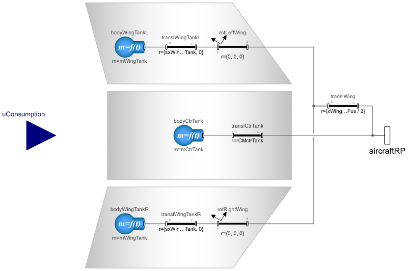
Diagram
Wolfram Language
In[1]:=

SystemModel["Aircraft.Physical.FixedWing.Parts.Propulsions.EnergyStorages.TankSystem"]
Out[1]:=
Information
This model extends the EnergyStorageBase model and calculates the size of the fuel tanks and the forces and torques acting on them as their masses change with the fuel consumption. This model is included in all propulsion system models with internal combustion engines, i.e. the TurbofanPropulsion, TurbojetPropulsion, TurbopropPropulsion and PistonPropulsion models.
Parameters
The tank parameters shown in Figure 1 are declared on the propulsion system level and propagated from there to this model. The tank system consists of three separate tanks, namely the two wing tanks on both sides of the main wing and the center tank in the fuselage. The user may choose to include either or both tank types inside the aircraft with the ctrTank and wingTank parameters.
The size of all tanks can be further adjusted downward from the estimated maximum possible tanks volume based on the wing and fuselage geometry with the tankFudgeFactor parameter. Furthermore, the initialFuel parameter allows the fueling level to easily be set as a fraction of the fuel capacity after the effect by the tankFudgeFactor parameter is considered.
The mass of the fuel inside the tanks is estimated with the estimated fuel tank volumes and the given fuel density regardless of whether the weight estimation method is used or not. However, if the exact volume of the fuel tanks is known for an aircraft, the equations estimating their values can be bypassed by entering the known values in the Estimated Fuel System Properties tab. Similarly, any known fuel tank center of mass location can be entered in the Estimated Fuel System Properties tab.
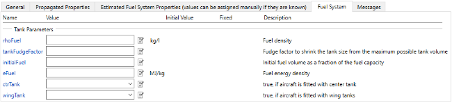
Figure 1: Tank parameters.
All other parameters of this model are propagated down from the AircraftBase model, and they are listed in the Propagated Properties tab. Thus, their values can and should be left unchanged in this model.
Tank Mass Properties
The maximum volumes of the wing and center fuel tanks are estimated with empirical relationships between the tank volumes and the geometry of the main wing and fuselage. The relationships are further described in section 3.4.5 in Reference [1]. The mass of the tanks only consists of the fuel mass inside them, and no mass is considered for the structure of the tanks. Thus, the mass of the tanks initially is the product of the estimated maximum fuel tank volume, the tankFudgeFactor parameter, the initialFuel parameter and the given fuel density (rhoFuel). As the fuel is consumed, the mass of the consumed fuel is subtracted from the initial tank masses of the center and wing tanks by adding a factor representing the share of the respective tank's capacity of the total fuel system capacity
![]()
![]() .
.
Thus, the ratios between the tank masses remain constant, and eventually all tanks will run out of fuel simultaneously. The mass of the consumed fuel is fed through the uConsumption port.
The center of mass location is solved individually for all three tanks, and they are assumed to remain constant even when the fuel is consumed. The derivation of the tank center of mass locations is described in detail in section 3.5.4 in Reference [1]. The fixed translations and rotations in this model are applied such that they generate translations of the tank center of mass locations with respect to the fuselage reference point, defined in the AircraftBase model.
The moments of inertia are also solved individually for all three tanks, and they change their values with the changing fuel tank masses. The complete calculations of the fuel tank moments of inertia are described in section 3.6.2 in Reference [1].
As the Modelica Standard Library component for 6DOF body only works with constant mass and inertia tensor, this library also includes a modified version of that component, the VariableMassBody component that calculates the Newton—Euler equations for a rigid body with variable mass and inertia tensor, which is used here to model the tanks.
The mass, center of mass and the inertia tensor of the total tank system are also calculated in this model, and they are used in the AircraftBase model to calculate the mass properties if the entire aircraft model. The variables for the tank system mass properties are declared in the EnergyStorageBase base class.
Energy
This model also calculates the total fuel burn rate of all engines combined (fuelBurnRate) and the total energy contained in the remaining fuel (Ef). In the EnergyStorageBase model, the first time derivative of the Ef value is calculated, which is the input power to the propulsion system (Pf).
References
[1] Erä-Esko, N. (2022). "Development and Use of System Modeler 6DOF Flight Mechanics Model in Aircraft Conceptual Design."
Available at: modelica://Aircraft/Resources/Documents/EraeEskoThesis.pdf.
Parameters (37)
| weightEst |
Type: Boolean Description: true, if weight estimation method is used for masses, center of mass location and inertia tensor |
|---|---|
| wFus |
Type: Length (m) Description: Fuselage maximum width |
| engineType |
Type: Integer Description: Type of engine (0 = piston, 1 = turboprop, 2 = turbojet, 3 = turbofan, 4 = electric) |
| VctrTank |
Value: if ctrTank then 2111 / 2750 * cWingRoot * tWingRoot * wFus else 0 Type: Volume (m³) Description: Center fuel tank volume |
| VwingTank |
Value: if wingTank then 0.54 * (SrefWing ^ 2 * tWingRoot * (1 + TRwing * sqrt(tauWing) + TRwing ^ 2 * tauWing)) / (bWing * cWingRoot * (1 + TRwing) ^ 2) else 0 Type: Volume (m³) Description: Wing fuel tank volume (both wings) |
| rCMctrTank |
Value: {xWingRootLE - cWingRoot / 2, 0, zWingRootLE} Type: Length[3] (m) Description: Center fuel tank center of mass coordinates w.r.t. fuselage reference point |
| rCMwingTankR |
Value: if wingTank then translWing.r + {sxWingTank, syWingTank * cos(gammaWing), -tan(gammaWing) * syWingTank * cos(gammaWing)} else {0, 0, 0} Type: Length[3] (m) Description: Right wing fuel tank center of mass coordinates w.r.t. fuselage reference point |
| rCMwingTankL |
Value: if wingTank then translWing.r + {sxWingTank, -syWingTank * cos(gammaWing), -tan(gammaWing) * syWingTank * cos(gammaWing)} else {0, 0, 0} Type: Length[3] (m) Description: Left wing fuel tank center of mass coordinates w.r.t. fuselage reference point |
| initialMctrTank |
Value: if weightEst then tankFudgeFactor * initialFuel * (VctrTank + VwingTank) * rhoFuel * (VctrTank / (VctrTank + VwingTank)) else initialMfuel * (VctrTank / (VctrTank + VwingTank)) Type: Mass (kg) Description: Initial fuel mass at center tank |
| initialMwingTank |
Value: if weightEst then tankFudgeFactor * initialFuel * (VctrTank + VwingTank) * rhoFuel * (0.5 * VwingTank / (VctrTank + VwingTank)) else initialMfuel * (0.5 * VwingTank / (VctrTank + VwingTank)) Type: Mass (kg) Description: Initial fuel mass at one wing tank |
| hWingTank |
Value: (0.7 * bWing - wFus) / (2 * cos(gammaWing)) Type: Length (m) Description: Parameter of trapezoidal wing fuel tank |
| aWingTank |
Value: cWingRoot + 0.96 * hWingTank * (cWingTip - cWingRoot) / (bWing - wFus) Type: Length (m) Description: Parameter of trapezoidal wing fuel tank |
| bWingTank |
Value: 0.48 * cWingRoot Type: Length (m) Description: Parameter of trapezoidal wing fuel tank |
| cWingTank |
Value: 0.3 * hWingTank * (cWingTip - cWingRoot) / (bWing - wFus) + hWingTank * lambdaWingLE Type: Length (m) Description: Parameter of trapezoidal wing fuel tank |
| sxWingTank |
Value: 0.25 * cWingRoot - lambdaWingLE * wFus / 2 - 0.15 * cWingRoot - (2 * aWingTank * cWingTank + aWingTank ^ 2 + cWingTank * bWingTank + aWingTank * bWingTank + bWingTank ^ 2) / (3 * (aWingTank + bWingTank)) Type: Length (m) Description: Parameter of trapezoidal wing fuel tank |
| syWingTank |
Value: wFus / (2 * cos(gammaWing)) + hWingTank / 3 * (2 * aWingTank + bWingTank) / (aWingTank + bWingTank) Type: Length (m) Description: Parameter of trapezoidal wing fuel tank |
| initialMfuel |
Type: Mass (kg) Description: Initial fuel mass |
| bWing |
Type: Length (m) Description: Main wing span |
| cWingRoot |
Type: Length (m) Description: Main wing root chord (where wing intersects with fuselage) |
| cWingTip |
Type: Length (m) Description: Main wing tip chord |
| tWingRoot |
Type: Length (m) Description: Main wing root thickness |
| tWingTip |
Type: Length (m) Description: Main wing tip thickness |
| xWingRootLE |
Type: Length (m) Description: Main wing root leading edge x-coordinate w.r.t. fuselage reference point (positive x-axis towards nose) |
| zWingRootLE |
Type: Length (m) Description: Main wing root leading edge z-coordinate w.r.t. fuselage reference point (positive z-axis towards ground) |
| lambdaWing |
Type: Angle (rad) Description: Main wing sweep angle at 1/4 chord |
| gammaWing |
Type: Angle (rad) Description: Main wing dihedral angle |
| iWing |
Type: Angle (rad) Description: Main wing incidence angle |
| SrefWing |
Type: Area (m²) Description: Main wing reference area |
| TRwing |
Type: Real Description: Main wing taper ratio |
| tauWing |
Type: Real Description: Ratio of thickness-to-chord ratios at the main wing tip and root |
| lambdaWingLE |
Type: Angle (rad) Description: Main wing leading edge sweep angle |
| rhoFuel |
Type: Density (kg/m³) Description: Fuel density |
| tankFudgeFactor |
Type: Real Description: Fudge factor to shrink the tank size from the maximum possible tank volume |
| initialFuel |
Type: Real Description: Initial fuel volume as a fraction of the fuel capacity |
| eFuel |
Type: SpecificEnergy (J/kg) Description: Fuel energy density |
| ctrTank |
Type: Boolean Description: true, if aircraft is fitted with center tank |
| wingTank |
Type: Boolean Description: true, if aircraft is fitted with wing tanks |
Outputs (1)
| xEf |
Type: Energy (J) Description: State of energy storage energy |
|---|
Connectors (2)
Components (9)
| translCtrTank |
Type: FixedTranslation Description: Position of center tank w.r.t fuselage reference point |
|
|---|---|---|
| translWing |
Type: FixedTranslation Description: Position of the main wing root quarter chord (inside fuselage) w.r.t fuselage reference point |
|
| rotRightWing |
Type: FixedRotation Description: Rotation of right wing around dihedral and wing incidence angle |
|
| rotLeftWing |
Type: FixedRotation Description: Rotation of left wing around dihedral and wing incidence angle |
|
| translWingTankR |
Type: FixedTranslation Description: Position of the right wing fuel tank center of mass w.r.t. wing root quarter chord (inside fuselage) |
|
| translWingTankL |
Type: FixedTranslation Description: Position of the left wing fuel tank center of mass w.r.t. wing root quarter chord (inside fuselage) |
|
| bodyWingTankL |
Type: VariableMassBody Description: Mass and inertia of left wing tank |
|
| bodyWingTankR |
Type: VariableMassBody Description: Mass and inertia of right wing tank |
|
| bodyCtrTank |
Type: VariableMassBody Description: Mass and inertia of center tank |
Used in Components (1)
|
Aircraft.Physical.FixedWing.HS121Trident Propulsion model for Hawker Siddeley HS-121 Trident 3B |