WOLFRAM SYSTEM MODELER
AileronsContribution from ailerons to aerodynamic forces |
|
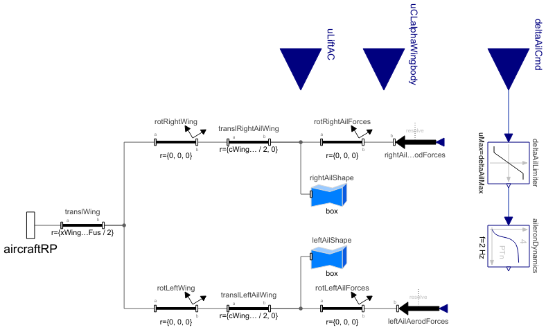
Diagram
Wolfram Language
In[1]:=
SystemModel["Aircraft.Physical.FixedWing.Parts.ControlSurfaces.Components.Ailerons"]
Out[1]:=
Information
This model calculates the aerodynamic forces due to aileron deflection. All parameters, including the ailerons specific parameters, are propagated to this model from the AircraftBase model, and therefore their values should not be changed here but only in the complete aircraft model. Additionally, the variables of the global flight conditions are propagated here from the AircraftBase model inside the flightData record. The mass properties of the ailerons (if the weight estimation method is used) are included in the equations in the WingBody component.
All forces in this model act on the supposed aerodynamic center of the ailerons, which is at quarter chord at half of the aileron span length. The position of the ailerons with respect to the fuselage reference point is solved based on the given y coordinates of the aileron root and tip (yAilRoot and yAilTp) and the main wing geometry. The equations to estimate the aerodynamic center location as well as any other estimated ailerons parameter can be bypassed by entering the known value in the Ailerons group in the Derived Properties parameter tab in the AircraftBase model.
The magnitudes of the aerodynamic forces acting along the body x and z axes due to ailerons deflection are solved by using the lateral control coefficients for yaw moment due to ailerons deflection (CnDeltaAil) and roll moment due to ailerons deflection (ClDeltaAil), respectively. The derivation of the normalized lateral control coefficients CnDeltaAil and ClDeltaAil, and their conversions into forces by multiplying them by correct factors are performed according to the method presented by Nelson [1]. The empirical factor kCnDeltaAil (KC,n,δa) used for solving CnDeltaAil, is calculated based on a formula presented in section 3.3.4 in Reference [2].
The aerodynamic forces due to ailerons deflection are applied with opposite signs in each side of the main wing as the ailerons are set to always deflect symmetrically but in opposite directions. The signs follow the sign convention of control surface deflections presented in ControlSurfaces.Conventional.
References
[1] Nelson, R. C. (1998) Flight Stability and Automatic Control. 2nd ed. McGraw-Hill.
Available at: http://home.eng.iastate.edu/~shermanp/AERE355/lectures/Flight_Stability_and_Automatic_Control_N.pdf.
[2] Erä-Esko, N. (2022). "Development and Use of System Modeler 6DOF Flight Mechanics Model in Aircraft Conceptual Design."
Available at: modelica://Aircraft/Resources/Documents/EraeEskoThesis.pdf.
Parameters (25)
| weightEst |
Type: Boolean Description: true, if weight estimation method is used for masses, center of mass location and inertia tensor |
|---|---|
| xCMdry |
Type: Length (m) Description: Aircraft center of mass x-coordinate w.r.t. fuselage reference point (with total mass for electric aircraft and gliders, positive x-axis towards nose) |
| wFus |
Type: Length (m) Description: Fuselage maximum width |
| bWing |
Type: Length (m) Description: Main wing span |
| cWingRoot |
Type: Length (m) Description: Main wing root chord (where wing intersects with fuselage) |
| xWingRootLE |
Type: Length (m) Description: Main wing root leading edge x-coordinate w.r.t. fuselage reference point (positive x-axis towards nose) |
| zWingRootLE |
Type: Length (m) Description: Main wing root leading edge z-coordinate w.r.t. fuselage reference point (positive z-axis towards ground) |
| lambdaWing |
Type: Angle (rad) Description: Main wing sweep angle at 1/4 chord |
| gammaWing |
Type: Angle (rad) Description: Main wing dihedral angle |
| iWing |
Type: Angle (rad) Description: Main wing incidence angle |
| SrefWing |
Type: Area (m²) Description: Main wing reference area |
| cWingMean |
Type: Length (m) Description: Main wing mean chord length |
| yWingAC |
Type: Length (m) Description: Main wing aerodynamic center from fuselage centerline (y-coordinate w.r.t. fuselage centerline of mean chord) |
| lambdaWingLE |
Type: Angle (rad) Description: Main wing leading edge sweep angle |
| lambdaWingTE |
Type: Angle (rad) Description: Main wing trailing edge sweep angle |
| cAil |
Type: Length (m) Description: Aileron average chord |
| yAilRoot |
Type: Length (m) Description: Aileron root y-coordinate w.r.t. fuselage centerline |
| yAilTip |
Type: Length (m) Description: Aileron tip y-coordinate w.r.t. fuselage centerline |
| cAilWingRoot |
Type: Length (m) Description: Local main wing chord at aileron root |
| cAilWingTip |
Type: Length (m) Description: Local main wing chord at aileron tip |
| yAilAC |
Type: Length (m) Description: Aileron aerodynamic center y-coordinate w.r.t. fuselage centerline |
| kCnDeltaAil |
Type: Real Description: Empirical factor for the yaw moment derivative due to ailerons |
| tauAil |
Type: Real Description: Aileron effectiveness parameter |
| deltaAilMax |
Type: Angle (rad) Description: Maximum aileron deflection |
| CADshapes |
Type: Boolean Description: true, if external CAD files are used for animation |
Inputs (1)
| flightData |
Type: FlightData Description: Global flight data variables |
|---|
Connectors (4)
| aircraftRP |
Type: Frame_b Description: Connector to aircraft reference point |
|
|---|---|---|
| deltaAilCmd |
Type: RealInput Description: Ailerons deflection command |
|
| uLiftAC |
Type: RealInput Description: Total lift force |
|
| uCLalphaWingbody |
Type: RealInput Description: Change in lift coefficient of the wing-body due to alpha |
Components (14)
| flightData |
Type: FlightData Description: Global flight data variables |
|
|---|---|---|
| rightAilAerodForces |
Type: WorldForce Description: Aerodynamic forces from right aileron |
|
| leftAilAerodForces |
Type: WorldForce Description: Aerodynamic forces from left aileron |
|
| aileronDynamics |
Type: CriticalDamping Description: Simplified model of the aileron actuator dynamics |
|
| deltaAilLimiter |
Type: Limiter Description: Limits aileron deflection to its assigned limits |
|
| translWing |
Type: FixedTranslation Description: Position of the main wing root quarter chord (inside fuselage) w.r.t fuselage reference point |
|
| rotRightWing |
Type: FixedRotation Description: Rotation of right wing around dihedral and wing incidence angle |
|
| rotLeftWing |
Type: FixedRotation Description: Rotation of left wing around dihedral and wing incidence angle |
|
| rotRightAilForces |
Type: FixedRotation Description: Rotation of aerodynamic forces acting on right aileron around dihedral and wing incidence angle |
|
| rotLeftAilForces |
Type: FixedRotation Description: Rotation of aerodynamic forces acting on left aileron around dihedral and wing incidence angle |
|
| translRightAilWing |
Type: FixedTranslation Description: Position of right aileron w.r.t. wing root quarter chord (inside fuselage) |
|
| translLeftAilWing |
Type: FixedTranslation Description: Position of left aileron w.r.t. wing root quarter chord (inside fuselage) |
|
| rightAilShape |
Type: FixedShape Description: Visualization of right aileron |
|
| leftAilShape |
Type: FixedShape Description: Visualization of left aileron |
Used in Components (1)
|
Aircraft.Physical.FixedWing.Parts.ControlSurfaces Model of system of surfaces in conventional wing configuration |