WOLFRAM SYSTEM MODELER
ConventionalModel of system of surfaces in conventional wing configuration |
|
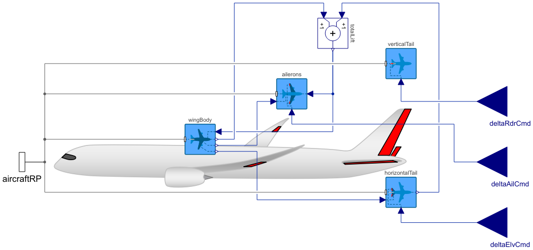
Diagram
Wolfram Language
In[1]:=
SystemModel["Aircraft.Physical.FixedWing.Parts.ControlSurfaces.Conventional"]
Out[1]:=
Information
This model compiles the WingBody, Ailerons, HorizontalTail and VerticalTail components into a system of surfaces of an aircraft with conventional wing configuration for modeling the aerodynamic forces and moments due to the presence of the surfaces and the deflection of the control suraces. The magnitude of the aerodynamic forces and moments are indeed solved in their respective individual surface models, but they require input from one another, and this model serves for distributing the signal between the surface models.
This model also propagates the required parameters and the variables of the flight conditions from the AircraftBase model further into the surface models. Additionally, if the weight estimation method is used, the calculations to estimate the mass properties of the main wing and the tail are performed in the respective models.
The inputs to this model are the control surface deflections, namely the elevator delflection (δe, deltaElvCmd), ailerons deflection (δa, deltaAilCmd) and rudder deflection (δr, deltaRdrCmd). Figure 1 shows the positive directions of control surface deflection angles as well as the body angular velocities and moments. All surface models are connected here to the aircraft reference point frame (aircraftRP), and the translations and rotations of each surface with respect to the aircraft reference point are included in the respective surface models.

Figure 1: Sign convention of control surface deflections, body angular velocities and moments [1].
For the horizontal and vertical tails, the contributions from their control surfaces, i.e. elevator and rudder, are integrated into the calculations of their aerodynamic forces, whereas the ailerons have their dedicated model to calculate their contribution to aerodynamic forces and moments.
References
[1] Erä-Esko, N. (2022). "Development and Use of System Modeler 6DOF Flight Mechanics Model in Aircraft Conceptual Design."
Available at: modelica://Aircraft/Resources/Documents/EraeEskoThesis.pdf.
Parameters (105)
| weightEst |
Type: Boolean Description: true, if weight estimation method is used for masses, center of mass location and inertia tensor |
|---|---|
| xCMdry |
Type: Length (m) Description: Aircraft center of mass x-coordinate w.r.t. fuselage reference point (with total mass for electric aircraft and gliders, positive x-axis towards nose) |
| zCMdry |
Type: Length (m) Description: Aircraft center of mass z-coordinate w.r.t. fuselage reference point (with total mass for electric aircraft and gliders, positive z-axis towards ground) |
| MTOMdes |
Type: Mass (kg) Description: Design maximum take-off mass |
| machDes |
Type: Real Description: Design Mach number |
| compMat |
Type: Boolean Description: true, if composite materials are used in structures |
| qMax |
Type: Pressure (Pa) Description: Maximum dynamic pressure |
| nMax |
Type: Real Description: Maximum load factor |
| lFus |
Type: Length (m) Description: Fuselage length |
| wFus |
Type: Length (m) Description: Fuselage maximum width |
| hFus |
Type: Length (m) Description: Fuselage maximum height |
| dFusHT |
Type: Length (m) Description: Fuselage diameter at horizontal tail 1/4 chord |
| SwetFus |
Type: Area (m²) Description: Fuselage wetted area |
| FFfus |
Type: Real Description: Fuselage form factor |
| bWing |
Type: Length (m) Description: Main wing span |
| cWingRoot |
Type: Length (m) Description: Main wing root chord (where wing intersects with fuselage) |
| cWingTip |
Type: Length (m) Description: Main wing tip chord |
| tWingRoot |
Type: Length (m) Description: Main wing root thickness |
| xWingRootLE |
Type: Length (m) Description: Main wing root leading edge x-coordinate w.r.t. fuselage reference point (positive x-axis towards nose) |
| zWingRootLE |
Type: Length (m) Description: Main wing root leading edge z-coordinate w.r.t. fuselage reference point (positive z-axis towards ground) |
| lambdaWing |
Type: Angle (rad) Description: Main wing sweep angle at 1/4 chord |
| gammaWing |
Type: Angle (rad) Description: Main wing dihedral angle |
| iWing |
Type: Angle (rad) Description: Main wing incidence angle |
| SrefWing |
Type: Area (m²) Description: Main wing reference area |
| ARwing |
Type: Real Description: Main wing aspect ratio |
| TRwing |
Type: Real Description: Main wing taper ratio |
| cWingMean |
Type: Length (m) Description: Main wing mean chord length |
| xWingAC |
Type: Length (m) Description: Main wing aerodynamic center from wing leading edge at mean chord (positive x-axis towards nose) |
| yWingAC |
Type: Length (m) Description: Main wing aerodynamic center from fuselage centerline (y-coordinate w.r.t. fuselage centerline of mean chord) |
| SwetWing |
Type: Area (m²) Description: Main wing wetted area |
| lambdaWingLE |
Type: Angle (rad) Description: Main wing leading edge sweep angle |
| lambdaWingHC |
Type: Angle (rad) Description: Main wing half-chord sweep angle |
| lambdaWingTE |
Type: Angle (rad) Description: Main wing trailing edge sweep angle |
| FFwing |
Type: Real Description: Main wing form factor |
| sdWing |
Type: Real Description: Fuselage drag factor for main wing |
| kdWing |
Type: Real Description: Empirical constant for Oswald efficiency factor for main wing |
| cAil |
Type: Length (m) Description: Aileron average chord |
| yAilRoot |
Type: Length (m) Description: Aileron root y-coordinate w.r.t. fuselage centerline |
| yAilTip |
Type: Length (m) Description: Aileron tip y-coordinate w.r.t. fuselage centerline |
| yAilAC |
Type: Length (m) Description: Aileron aerodynamic center y-coordinate w.r.t. fuselage centerline |
| cAilWingRoot |
Type: Length (m) Description: Local main wing chord at aileron root |
| cAilWingTip |
Type: Length (m) Description: Local main wing chord at aileron tip |
| kCnDeltaAil |
Type: Real Description: Empirical factor for the yaw moment derivative due to ailerons |
| tauAil |
Type: Real Description: Aileron effectiveness parameter |
| bHT |
Type: Length (m) Description: Horizontal tail span |
| cHTroot |
Type: Length (m) Description: Horizontal tail root chord |
| cHTtip |
Type: Length (m) Description: Horizontal tail tip chord |
| tHTroot |
Type: Length (m) Description: Horizontal tail root thickness |
| zHTrootLE |
Type: Length (m) Description: Horizontal tail root leading edge z-coordinate w.r.t. fuselage reference point (positive z-axis towards ground) |
| lambdaHT |
Type: Angle (rad) Description: Horizontal tail sweep angle at 1/4 chord |
| iHT |
Type: Angle (rad) Description: Horizontal tail incidence angle |
| Selv |
Type: Area (m²) Description: Elevator area |
| SrefHT |
Type: Area (m²) Description: Horizontal tail reference area |
| ARht |
Type: Real Description: Aspect ratio of horizontal tail |
| TRht |
Type: Real Description: Taper ratio of horizontal tail |
| cHTmean |
Type: Length (m) Description: Horizontal tail mean chord |
| lHTcm |
Type: Length (m) Description: Horizontal tail arm length (from aircraft center of mass to horizontal tail 1/4 chord) |
| lHTwingAC |
Type: Length (m) Description: Horizontal tail arm length (from wing aerodynamic center to horizontal tail 1/4 chord) |
| SwetHT |
Type: Area (m²) Description: Horizontal tail wetted area |
| lambdaHTle |
Type: Angle (rad) Description: Horizontal tail leading edge sweep angle |
| FFht |
Type: Real Description: Horizontal tail form factor |
| sdHT |
Type: Real Description: Fuselage drag factor for horizontal tail |
| kdHT |
Type: Real Description: Empirical constant for Oswald efficiency factor for horizontal tail |
| tauElv |
Type: Real Description: Elevator effectiveness parameter |
| bVT |
Type: Length (m) Description: Vertical tail span |
| cVTroot |
Type: Length (m) Description: Vertical tail root chord |
| cVTtip |
Type: Length (m) Description: Vertical tail tip chord |
| tVTroot |
Type: Length (m) Description: Vertical tail root thickness |
| zVTroot |
Type: Length (m) Description: Vertical tail root z-coordinate w.r.t fuselage reference point |
| lambdaVT |
Type: Angle (rad) Description: Vertical tail sweep angle at 1/4 chord |
| Srdr |
Type: Area (m²) Description: Rudder area |
| SrefVT |
Type: Area (m²) Description: Vertical tail reference area |
| ARvt |
Type: Real Description: Aspect ratio of vertical tail |
| TRvt |
Type: Real Description: Taper ratio of vertical tail |
| cVTmean |
Type: Length (m) Description: Vertical tail mean chord |
| lVTcm |
Type: Length (m) Description: Vertical tail arm length (from aircraft center of mass to vertical tail 1/4 chord) |
| lVTwingAC |
Type: Length (m) Description: Vertical tail arm length (from wing aerodynamic center to vertical tail aerodynamic center) |
| zVTac |
Type: Length (m) Description: Vertical tail center of pressure z-coordinate w.r.t. fuselage reference point |
| SwetVT |
Type: Area (m²) Description: Vertical tail wetted area |
| lambdaVTle |
Type: Angle (rad) Description: Vertical tail leading edge sweep angle |
| FFvt |
Type: Real Description: Vertical tail form factor |
| sdVT |
Type: Real Description: Fuselage drag factor for vertical tail |
| kdVT |
Type: Real Description: Empirical constant for Oswald efficiency factor for vertical tail |
| tauRdr |
Type: Real Description: Rudder effectiveness parameter |
| sigmaBeta |
Type: Real Description: Change in sidewash due to beta |
| kSkinFus |
Type: Length (m) Description: Fuselage surface roughness height |
| CDmaxFus |
Type: Real Description: Maximum drag coefficient of the fuselage |
| kSkinWing |
Type: Length (m) Description: Main Wing surface roughness height |
| ClAlphaWing2D |
Type: CurveSlope (rad⁻¹) Description: Change in the section lift coefficient of the main wing airfoil (2D) due to alpha |
| alpha0Wing2D |
Type: Angle (rad) Description: Zero-lift angle of attack of the main wing airfoil (2D) |
| CLmaxWing3D |
Type: Real Description: Maximum lift coefficient of the main wing (3D) |
| CDmaxWing3D |
Type: Real Description: Maximum drag coefficient of the main wing (3D) |
| kSkinHT |
Type: Length (m) Description: Horizontal tail surface roughness height |
| ClAlphaHT2D |
Type: CurveSlope (rad⁻¹) Description: Change in the section lift coefficient of the horizontal tail airfoil (2D) due to alpha |
| alpha0HT2D |
Type: Angle (rad) Description: Zero-lift angle of attack of the horizontal tail airfoil (2D) |
| CLmaxHT3D |
Type: Real Description: Maximum lift coefficient of the horizontal tail (3D) |
| CDmaxHT3D |
Type: Real Description: Maximum drag coefficient of the horizontal tail (3D)*(SrefHT/SrefWing) |
| kSkinVT |
Type: Length (m) Description: Vertical tail surface roughness height |
| ClAlphaVT2D |
Type: CurveSlope (rad⁻¹) Description: Change in the section lift coefficient of the vertical tail airfoil (2D) due to alpha |
| deltaElvMax |
Type: Angle (rad) Description: Maximum elevator deflection |
| deltaAilMax |
Type: Angle (rad) Description: Maximum aileron deflection |
| deltaRdrMax |
Type: Angle (rad) Description: Maximum rudder deflection |
| CADshapes |
Type: Boolean Description: true, if external CAD files are used for animation |
| rho0 |
Type: Density (kg/m³) Description: Air density at sea-level |
| a0 |
Type: Velocity (m/s) Description: Speed of sound at sea-level |
Inputs (1)
| flightData |
Type: FlightData Description: Global flight data variables |
|---|
Connectors (4)
Components (6)
| flightData |
Type: FlightData Description: Global flight data variables |
|
|---|---|---|
| wingBody |
Type: WingBody Description: Model for drag and lift forces due to main wing and fuselage |
|
| horizontalTail |
Type: HorizontalTail Description: Model for lift and drag forces due to horizontal tail and elevator |
|
| verticalTail |
Type: VerticalTail Description: Model for lift and drag forces due to vertical tail and rudder |
|
| ailerons |
Type: Ailerons Description: Model for lift and drag forces due to ailerons |
|
| totalLift |
Type: Add Description: Summing of the lift force components |
Used in Components (1)
|
Aircraft.Physical.FixedWing.Interfaces Interface for a complete aircraft model |