WOLFRAM SYSTEM MODELER
GettingStartedGetting Started |
|
Wolfram Language
In[1]:=
SystemModel["Aircraft.GettingStarted"]
Out[1]:=

Information
The Aircraft library enables the user to model and simulate the flight of an aircraft. The guide begins by introducing the multi-rotor model, which is comparatively straightforward, and then follows with the fixed-wing model, which first introduces how the modeling of flight of an existing aircraft is done manually. Afterwards, a model of flight controlled by an autopilot is shown.
A general introduction to the theory for modeling the flight of an aircraft and the contents of the Aircraft library are presented in the Introduction. For a more detailed exploration tailored to fixed-wing aircraft and rotary-wing aircraft, refer to FixedWing.Introduction and RotaryWing.Introduction, respectively. Basic knowledge of System Modeler is assumed for this guide. We recommend that you first have a look at the learning resources at http://www.wolfram.com/system-modeler/resources if you are not familiar with System Modeler.
The Aircraft library contains two modeling environments in which an airplane and its flight can be modeled and simulated. There are two types of fixed-wing aircraft models, one nonlinear physical and one linear state space. The following sections introduce how to set up the flight of the physical fixed-wing aircraft, which is the main model of the library. For modeling the state space airplane, refer to Aircraft.StateSpace.
Simulating the Flight of a Quadrotor with Pre-determined Reference Trajectory
In any quadrotor example, three essential components are required. First, there is the physical structure of the quadrotor, known as the Aircraft.Physical.RotaryWing.MultiRotor.Quadrotor, including the quadrotorBody, propulsion system and sensors. Achieving stable flight requires a connection to a controller or a set of controllers responsible for position and attitude stabilization that can be found in Aircraft.ControlSystems.MultiRotorControllers. These controllers should be connected to the desired input sets, including three position inputs and the yaw angle.
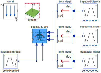
Figure 1: Diagram view of the trajectory tracking of the quadrotor model
Figure 1 depicts the diagram view of the top-level model to simulate the trajectory tracking of a quadrotor with a pre-determined reference trajectory. Starting from the Quadrotor, the input comprises a control command vector for each propulsion system, and the output consists of sensor measurements for the translational and rotational states of the quadrotor. The quadrotor is connected to the PositionAttitude controller, which takes in the reference position and yaw angle to generate a voltage command for the motor. Users can specify the position input through the reference trajectory component, offering options such as circular, infinity and eight-shape trajectories, or individually define each position component using the Modelica.Blocks.Sources.TimeTable component. The Visualization component is introduced for animation purposes. A more comprehensive explanation of the dynamics of the quadrotor and the parameters of its components is provided in the Introduction.
Simulating the Flight of a Nonlinear Physical Aircraft Model Manually
Figure 2 depicts the diagram view of a top-level model to simulate the flight of the physical Boeing 737-800 airplane. The aircraft can be any model that extends the Physical.FixedWing.Interfaces.AircraftBase, so it may be any of the existing airplanes from Aircraft.Physical.FixedWing.
The inputs for the physical aircraft model are the control commands for the control actuators, i.e. deflection angles in radians for ailerons (deltaAilCmd), elevator (deltaElvCmd) and rudder (deltaRdrCmd). In this example, zero deflection is given to the ailerons and rudder, but a minor deflection of -2 degrees is given to the elevator so the aircraft flies close to trim condition.
The throttle input is given by the vector deltaThrotCmd[nEng] (with a size equivalent to the number of engines of the aircraft) in a unitless normalized ratio ranging from 0 to 1. The times the input is connected to the model must match the number of engines of the aircraft. That is, the constantThrottle input in Figure 2 must be connected twice: once for each engine (one to boeing737800.deltaThrotCmd[1] and once for boeing737800.deltaThrotCmd[2], respectively).
Of particular significance is to declare the initial conditions at which the airplane is flying by setting up the initialAltitude & initialVelocity variables to a suitable value. For this example, initialAltitude=15000 ft and initialVelocity =800 km/s. This should be done at the bottom part of the parameters´ General Tab under the Initialization group of any fixed-wing physical aircraft model. The physical model also requires the Aircraft.World model for representing the world frame fixed on the Earth and for modeling the gravity field. A non-rotating flat-Earth model is applied, and thus the origin of the world is an arbitrary point on the surface of the Earth. The orientation of the coordinate systems is presented further in Aircraft.Introduction. Several examples of this can be found in the Aircraft.Examples package.
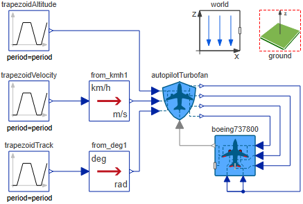
Figure 2: Diagram view of basic model to simulate the flight of a physical aircraft model by giving control commands directly to the control actuators and the engines.
Simulating the Flight of a Nonlinear Physical Aircraft Model Using an Autopilot
For simulating the flight of a physical aircraft model controlled by an autopilot, a suitable autopilot extending to the Autopilots.Interfaces.AutopilotBase model is to be added to the top-level model together with the physical aircraft model. It is of utmost importance to declare the nEng parameter of the autopilot to match the aircraft's number of engines. For better results, match the type of autopilot available from Aircraft.ControlSystems.Autopilot to the aircraft's type of engine.
Contrary to manual flight, the autopilot's inputs are not control surface deflections, but rather navigational inputs. These are: altitude, track and velocity (with variables altCmd, trackCmd and vTotCmd, respectively) in standard SI units (m, m/s, rad). The outputs should be connected in the way that deltaAilCmd, deltaElvCmd and deltaRdrCmd match for both the autopilot and the aircraft. Converters from the Modelica.Blocks.Math.UnitConversions package may be used to enable entering the flight trajectory commands in other units, as shown in Figure 3.
The thrust is controlled through the autopilot.deltaThrotCmd[nEng] output vector. Once the the nEng parameter of the autopilot matches the aircraft's number of engines, the easiest way to set up this connection is by declaring from autopilot.deltaThrotCmd[:] to boeing737800.deltaThrotCmd[:] on the Add Connection window. In this way, all of the aircraft engines receive the same throttle commands from the autopilot.
The feedback signals to the autopilot's flightDataIn connector are sent through the flightDataOut connector of the aircraft model. Last, the aircraft model needs to be initialized by entering initial values for the initialAltitude & initialVelocity parameters. These should not differ drastically from the inputs given to the autopilot (e.g. if altCmd=1000 and initialAltitude=10, a singlularity on the autopilot could be encountered). For flights with varying navigation commands, the autopilot inputs can be instead Modelica.Blocks.Sources.TimeTable. In this way, a specific altitude, velocity or track input will be given to the autopilot at a specific time.
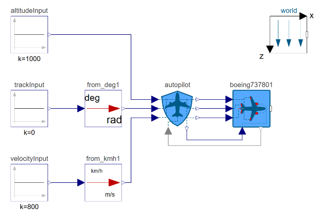
Figure 3: Diagram view of basic model to simulate the flight of a physical aircraft model controlled by an autopilot.
Visualizing Important Variables on the Simulation Center
After the simulation is run, the most relevant variables are found in the flightData record of the aircraft model. Navigationwise, these include the geometric altitude (alt), total velocity (vTot). Positionwise, they include the so-called Euler Angles roll Φ (phi), pitch θ (theta) and yaw Ψ (psi) as well as its rate of change (velocity and accelerations). The most important aerodynamic variables such as angle of attack α (alpha), sideslip β (beta) and flight path γ (gamma) are also found here. Other important coefficients such as the ones for lift (controlSurfaces.wingBody.CLac), parasitic drag (CD0), induced drag (CDi) and total drag of the aircraft (CDac) are also located in the same place. These can be found easily by searching for them on the Plot search bar.
Creating a New Physical Aircraft Model with Known Mass Properties
A new physical aircraft model can be modeled by creating a new model that extends the Physical.FixedWing.Interfaces.AircraftBase aircraft model. All properties are entered on the top level of this new aircraft model.
The engine model to be used in the aircraft is also selected as the Engine parameter from the drop-down list in the General tab of the propulsion component from the list of modeled engines. This must match the type of engine declared on the top level of the aircraft. A new engine model can be modeled through creating a new model that extends the engine base models (TurbofanEngine, TurbojetEngine, TurbopropEngine, PistonEngine and ElectricEngine) and filling the required parameters. After doing so, the new engine model appears in the drop-down menu for the Engine parameter.
When an existing aircraft design with known mass properties is to be modeled, the weightEst parameter in the Mass and Inertia tab is set to false. This enables the editing of only the relevant parameters further down. More detailed instructions about how to fill the parameters of the Physical.FixedWing.Interfaces.AircraftBase model and information about the parameters themselves are found in its documentation.
References
[1] Erä-Esko, N. (2022). Development and Use of System Modeler 6DOF Flight Mechanics Model in Aircraft Conceptual Design. Available at: modelica://Aircraft/Resources/Documents/EraeEskoThesis.pdf.
[2] Nelson, R. C. (1998). Flight Stability and Automatic Control. 2nd ed. McGraw-Hill.
[3] Cook, M. A. (2012). Flight Dynamics Principles. 2nd ed. Butterworth Heinemann.