WOLFRAM SYSTEM MODELER
PositionAttitudePIDControl the position and attitude of the quadrotor through PID controllers |
|
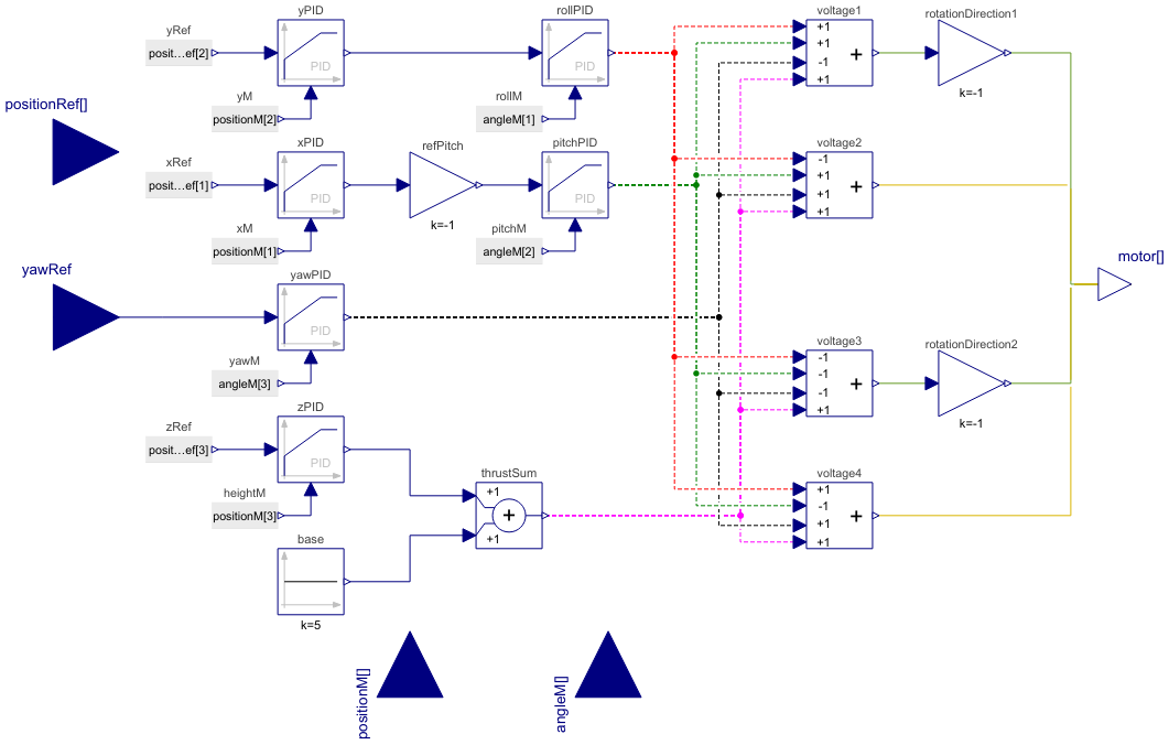
Diagram
Wolfram Language
In[1]:=
SystemModel["Aircraft.ControlSystems.MultiRotorControllers.PositionAttitudePID"]
Out[1]:=
Information
Controlling a quadcopter is a challenging and intriguing task due to its six degrees of freedom, consisting of three rotational and three translational movements. What adds to the complexity is that quadcopters are underactuated systems, with only four independent inputs available (rotor speeds). Consequently, achieving all six degrees of freedom involves coupling between rotational and translational motions.The quadrotor dynamics are highly nonlinear, and the complex aerodynamic effects further add to the challenge. Unlike ground vehicles, quadcopters have very little friction, making it difficult to prevent motion, and they require their own damping to remain stable. These factors make quadcopter control an interesting and complex problem. To tackle this problem, a simplified model of quadcopter dynamics is used, and controllers are designed to follow a designated trajectory. [1]
The control system receives inputs in the form of a position vector denoted by (x, y, z) and a yaw angle, and it produces voltage signals for the quadrotor's four DC motors. To enable full control of the quadrotor in all six degrees of freedom, it is necessary to incorporate the roll and pitch angles into the controller. This is achieved by coupling x and y positions to the pitch (θ) and roll (φ) angles, respectively, through a cascade controller structure for longitudinal and lateral dynamics.
As illustrated in Figure 1, the outer lateral controller takes in the reference lateral position (yref), which originates from the user input command, and the measured lateral position (ymeasured) from the sensors. It uses these inputs to calculate the error in lateral position (ye). Following that, a LimPID controller is established for position control, where, given the small angle assumption [2], the resulting output corresponds to the reference roll angle (φref). Another LimPID is used to control roll angle (φ) and finally generates the roll moment change (M). A similar methodology is applied to the longitudinal control channel.
The yaw channel is controlled with a single LimPID controller and generates the yaw moment change (N) command.
In the case of the throttle command, the additional thrust increment should be added to the base thrust, which represents the minimum required thrust to overcome the weight of the quadrotor.
Finally, in the Mixer, the roll moment change (L), pitch moment change (M), yaw moment change (N) and throttle command will add up to allocate force and moments to each propeller. The outputs of the mixer and subsequently controller are the voltage of the DC motors.

Figure 1: Controller block diagram.
LimPID
The LimPID controller can be finely adjusted by modifying its proportional gain, integrator, derivative time constants and saturation limit. The saturation limit can be configured within the constraints defined by yMax and yMin, taking into account model limitations such as actuator deflection limits or motor RPM. Once the controller type in LimPID is selected, a combination of proportional, derivative and integral controllers can be configured to meet the desired control objectives.
Note: The controller gains should be tuned based on the specific quadrotor and mission requirements.
Reference
[1]: Astudillo, A., Muñoz, P., Álvarez, F., & Rosero, E. (2017, June). Altitude and attitude cascade controller for a smartphone-based quadcopter. In 2017 International Conference on Unmanned Aircraft Systems (ICUAS) (pp. 1447-1454). IEEE.
[2]: Noordin, A., Basri, M. A. M., & Mohamed, Z. (2020). Simulation and experimental study on PID control of a quadrotor MAV with perturbation. Bulletin of Electrical Engineering and Informatics, 9(5), 1811-1818.
Parameters (18)
| propGainY |
Value: 0.2 Type: Real Description: Gain of controller (yPID.k) |
|---|---|
| intTimeConstY |
Value: 10 Type: Time (s) Description: Time constant of Integrator block (yPID.Ti) |
| derTimeConstY |
Value: 0.6 Type: Time (s) Description: Time constant of Derivative block (yPID.Td) |
| propGainX |
Value: 0.2 Type: Real Description: Gain of controller (xPID.k) |
| intTimeConstX |
Value: 10 Type: Time (s) Description: Time constant of Integrator block (xPID.Ti) |
| derTimeConstX |
Value: 0.6 Type: Time (s) Description: Time constant of Derivative block (xPID.Td) |
| propGainZ |
Value: 100 Type: Real Description: Gain of controller (PIDHeight.k) |
| intTimeConstZ |
Value: 2 Type: Time (s) Description: Time constant of Integrator block (PIDHeight.Ti) |
| derTimeConstZ |
Value: 0.1 Type: Time (s) Description: Time constant of Derivative block (PIDHeight.Td) |
| propGainRoll |
Value: 20 Type: Real Description: Gain of controller (PIDRoll.k) |
| intTimeConstRoll |
Value: 0.47 Type: Time (s) Description: Time constant of Integrator block (PIDRoll.Ti) |
| derTimeConstRoll |
Value: 0.3 Type: Time (s) Description: Time constant of Derivative block (PIDRoll.Td) |
| propGainPitch |
Value: 20 Type: Real Description: Gain of controller (PIDPitch.k) |
| intTimeConstPitch |
Value: 0.47 Type: Time (s) Description: Time constant of Integrator block (PIDPitch.Ti) |
| derTimeConstPitch |
Value: 0.3 Type: Time (s) Description: Time constant of Derivative block (PIDPitch.Td) |
| propGainYaw |
Value: 10 Type: Real Description: Gain of controller (PIDYaw.k) |
| intTimeConstYaw |
Value: 0.1 Type: Time (s) Description: Time constant of Integrator block (PIDYaw.Ti) |
| derTimeConstYaw |
Value: 0.1 Type: Time (s) Description: Time constant of Derivative block (PIDYaw.Td) |
Connectors (5)
| positionRef |
Type: RealInput[3] Description: Reference position vector |
|
|---|---|---|
| yawRef |
Type: RealInput Description: Reference yaw angle |
|
| motor |
Type: RealOutput[4] Description: Voltage command to electric motor |
|
| positionM |
Type: RealInput[3] Description: Measured position of quadrotor |
|
| angleM |
Type: RealInput[3] Description: Measured angle of quadrotor |
Components (24)
| zPID |
Type: LimPID Description: PID controller generates z position (height) control command |
|
|---|---|---|
| yawPID |
Type: LimPID Description: PID controller generates yaw angle control command |
|
| pitchPID |
Type: LimPID Description: PID controller generates pitch angle control command |
|
| rollPID |
Type: LimPID Description: PID controller generates roll angle control command |
|
| yPID |
Type: LimPID Description: Y position PID controller generates the roll reference command |
|
| xPID |
Type: LimPID Description: X position PID controller generates the roll reference command |
|
| voltage2 |
Type: Add4 Description: Voltage command of the second electric motor |
|
| voltage3 |
Type: Add4 Description: Voltage command of the third electric motor |
|
| voltage4 |
Type: Add4 Description: Voltage command of the fourth electric motor |
|
| voltage1 |
Type: Add4 Description: Voltage command of the first electric motor |
|
| rotationDirection2 |
Type: Gain Description: Change rotation of the propeller to anticlockwise direction |
|
| rotationDirection1 |
Type: Gain Description: Change rotation of the propeller to clockwise direction |
|
| refPitch |
Type: Gain Description: The gain command of the pitch rotation |
|
| heightM |
Type: RealExpression Description: Measured z position (height) |
|
| yawM |
Type: RealExpression Description: Measured yaw angle |
|
| xM |
Type: RealExpression Description: Measured x position |
|
| yM |
Type: RealExpression Description: Measured y position |
|
| pitchM |
Type: RealExpression Description: Measured pitch angle |
|
| rollM |
Type: RealExpression Description: Measured roll angle |
|
| yRef |
Type: RealExpression Description: Reference y position |
|
| xRef |
Type: RealExpression Description: Reference x position |
|
| zRef |
Type: RealExpression Description: Reference z position |
|
| thrustSum |
Type: Add Description: The total of the basic thrust and the incremental thrust. |
|
| base |
Type: Constant Description: Base thrust value equivalent to the quadrotor weight |
Used in Examples (2)
|
Aircraft.Examples Circular path tracking by a quadrotor |
|
|
Aircraft.Examples Compare the impact of two types of controller structures on the motion of the quadrotor |