WOLFRAM SYSTEM MODELER
IntroductionIntroduction to the theory for modeling the flight of a quadrotor and to the contents of the RotaryWing package |
|
Wolfram Language
In[1]:=
SystemModel["Aircraft.Physical.RotaryWing.Introduction"]
Out[1]:=

Information
Introduction
With the Wolfram System Modeler Multirotor package, you can model and simulate the flight of the quadrotor and build up your own multirotor with even more than four rotors. The user can model a quadrotor knowing the mass and inertia, geometry and propulsion properties of an existing or a generic quadrotor. Thus, regarding the physical model of a drone, the current controller gains can be tuned or another control structure can be designed.
The motion of the quadrotor is modeled for a rigid body with six degrees of freedom, which encompasses the interconnections between various linear and angular motions along different axes, as well as the interactions between the control actuators and the quadrotor's motion.
Theory
This section includes only a short description of the theory behind the models.
Reference frame
The initial step in modeling a mechanical object involves choosing appropriate reference frames. In flight dynamics, typically two coordinate systems are used: the fixed reference frame (inertial reference frame) for describing the quadrotor's linear position and velocity, and the body reference frame, which is centered on the vehicle's mass and used for describing its orientation, applied forces and moments.
The inertial reference frame, known as North-East-Down (NED) arrangement, has its x and y axes aligned with meridian and parallel lines, respectively, while the third component points downward toward the Earth's center.
The choice of the body reference frame is crucial, as it affects both the inertia and actuator matrices. For quadrotors, there are two configurations to consider: the plus (+) and cross (×) configurations, each with its own set of pros and cons. In this simulation, the cross configuration is chosen. If a user wishes to switch to the plus (+) configuration, they would need to modify the equations for forces and moments. [1]
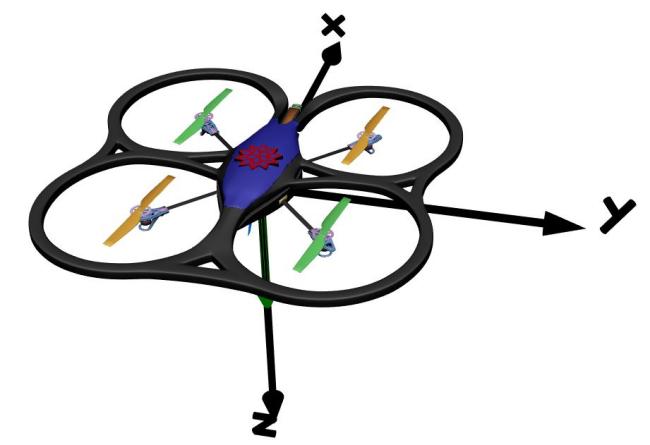
In the cross configuration, the first axis aligns with the vehicle's symmetry plane and points forward, the second axis extends to the right, and the third axis points downward. Figure 1 illustrates these reference frames.

Figure 1: Body and Inertia reference frames.
Transormations:
Euler angles, denoted as φ, θ, ψ, describe the orientation of a rigid body in 3D Euclidean space. They also define the orientation of one reference frame relative to another by transforming coordinates. Rotation matrices, denoted as R3, represent rotations around one, two or three axes. By multiplying rotation matrices around individual axes, an overall rotation matrix is obtained, capturing the rotation from one reference frame to another. For the quadrotor's body-to-inertial rotation matrix, the NASA standard rotation convention is applied. This involves a sequential rotation: first around the Z-axis by an angle ψ, followed by a rotation around the new intermediate Y-axis by an angle θ, and finally, a rotation around the newer X-axis by an angle φ.

Figure 2: Sequences of Euler angle rotations from world frame to body frame and the directions of positive Euler angles.
Below are the mathematical representations of rotation matrices.


Multiplying the three rotation matrices with the aforementioned sequence for a body-to-Earth transformation results in the so-called Euler rotation matrix.
![]()

To obtain the body angular velocity [p, q, r] from Euler angles, an additional transformation matrix is required.

Due to the inherent nonlinearity and strong coupling in quadcopter dynamics, linearization is performed around an equilibrium point, and to simplify the equations, small angle assumptions are applied. Therefore, under the small angle assumption (where the angle change is less than 15 degrees), sinα ≅ 0 and cosα ≅ 1, This leads to the following results:

Quadrotor Dynamics:
The basis of the aircraft dynamics calculations is Newton's second law for linear and angular motion. For linear (translational) motion it states that the external forces (aerodynamic, gravity and thrust) acting on the aircraft equal the time rate of change of the aircraft's momentum, whereas for angular motion the moments created by aerodynamic forces and thrust acting on the aircraft need to be equal to the time rate of change in angular momentum. ![]()
![]()
The moment equation is solved using the world referance frame. In the case of quadrotor dynamics and control, it is more useful to write the moments equation with respect to the body frame, which needs the rotation of the frame in the time derivative, resulting in the following equation:

where Mb is the total moment in the body reference frame, Ib is the inertia tensor in the body reference frame and ωb is the angular rotation speed vector.
As you can see in Figure 1, the summation of four upward forces generates the required lift force. Multiplying the lift force with arm length gives the resultant moment on the center of the mass. The resultant moment in hover is equal to zero following the right-hand rule so the quadrotor stays still in hover.
As you can see in the Figure 1, propellers 1 and 3 rotates clockwise while propellers 2 and 4 are rotating counter clockwise. The benefit of having two pairs of propellers rotating in opposite directions is that they cancel out moment generated by the rotation of each rotor and prevent the spin of the quadrotor. Imagine if all of them were rotating in the same direction: according to Newton's third law, the quadrotor would spin in the opposite direction of the rotation of the blades. Following this rotation arrangement, as shown in the Figure 2, a positive roll motion can be obtained from the increse in the increment of the rotation speed of propellers 2 and 3 and the same amount decrease of propellers 1 and 4, which requires a direction change of the propellers 3 and 4 as well. A poitive pitch results from generating an incremental positive lift force in the positive direction of propoellers 1 and 2 and the negative force increment of propellers 3 and 4. Finally, yaw motion comes from the rotation of all of the propellers in the same direction, which makes the quadrotor itself to spin in the opposite direction.


Figure 2: Angular motion.
Equation of Motion (EOM):
By defining the control command vector as [u1, u2, u3, u4] = [T, τφ, τθ, τψ], where T represents the lift force, τφ is the roll moment, τθ is the pitch moment and τψ is the yaw moment and then applying the Newton–Euler method, the rotational motion equation can be expressed as follows:

Here,η denotes the vector of Euler angles, expressed as η = [φ, θ, ψ], and I represents the inertia tensor of the quadrotor. The quadcopter's symmetrical configuration leads to the inertial matrix I being diagonal.

Substituting the inertia matrix into the rotational motion equation, the resultant equation is as follows:

Now, it is possible to derive the rotational equations of motion in terms of acceleration:

On the other hand, it is necessary to formulate the translational equation of motion to adjust the position of the quadrotor. To achieve this, we follow the Newton's second law:


where m represents the mass of the quadrotor, a is the translational acceleration vector, R is the Euler rotational matrix from the body to the Earth reference frame and FB is the total forces acting on the quadrotor in the body reference frame. Subsituting FB and R into the equation, we arrive to the translational equation of motion.

Once again, taking into account the small angle assumption, we can summarize the rotational and translational equations of motion as follows: [2]

Quadrotor Parameters:
Several parameters describing the quadrotor geometry, propulsion and mass properties are required to model it. The parameters can be set to different levels depending on their importance and the objective of the examples. The main parameters of the quadrotor are the mass and inertia of the central body and the propulsive system, the geometry and the propulsion system properties.
Controller
The controller is one of the most important parts of the quadrotor and its performance is highly related to the quadrotor body properties. Therefore, the controller gains should be tunned when the properties of the QuadrotorBody change. Two different controller stuctures based on the PID controller are presented in the MultiRotorControllers package.
Physical Model
The physical model of the quadrotor is a nonlinear model built with the Modelica Standard Library MultiBody components, and it models the flight dynamics of the quadrotor. The physical quadrotor model consists of three submodels for the mass properties and the propulsion and controller, which are described in this section.
Body
QuadrotorBody consists of the quadrotor's mass and inertia characteristics, as well as the arms connecting each propulsion system to the quadrotor's center of mass. Additionally, it includes a (CAD) model of the quadrotor for visualizing it in animations. The connectors of the propulsion frame are linked to the propulsion system in order to mount forces, moments and rotational speed to the quadrotor body.
Propulsion
The propulsion system includes the DC motor, Ideal Gear and Propeller. This system is responsible for transmitting the voltage commanded by the controller, thereby converting electrical energy into the forces and moments necessary for mounting on the QuadrotorBody propulsion frames.
Controller
The Control system is responsible for generating voltage signals for the quadrotor's four DC motors by receiving inputs, including a position vector (x, y, z) and a yaw angle, along with sensor measurements. These inputs are used to compute the appropriate command signal for drone control, which then feed into the DC motor.
Simplifications and Limitations
The strength of the RotaryWing package is that it models a realistic quadrotor model, and one can use it to model an already existing quadrotor or build it from scratch. However, certain simplifications have been employed, which narrow down the domain in which the models work realistically and accurately. Given that the quadrotor is a nonlinear model and the existing controller structure is founded on the linear PID controller technique, a small angle assumption has been incorporated. This assumption implies that trajectory tracking may not be precise, particularly for significant amplitude changes in the reference set points, especially in the x and y dimensions, and consequently, in the roll and pitch motion.
References
[1]: Rao, J., Li, B., Zhang, Z., Chen, D., & Giernacki, W. (2022). Position control of quadrotor UAV based on cascade fuzzy neural network. Energies, 15(5), 1763.
[2]: Wang, P., Man, Z., Cao, Z., Zheng, J., & Zhao, Y. (2016, November). Dynamics modelling and linear control of quadcopter. In 2016 International Conference on Advanced Mechatronic Systems (ICAMechS) (pp. 498-503). IEEE.