WOLFRAM SYSTEM MODELER
PropellerPropeller of the quadrotor with two blades |
|
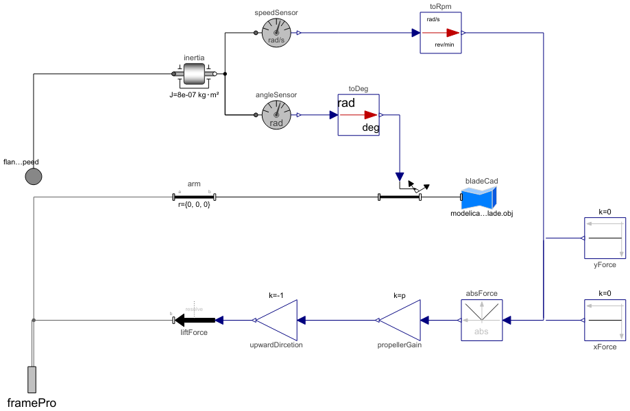
Diagram
Wolfram Language
In[1]:=
SystemModel["Aircraft.Physical.RotaryWing.MultiRotor.Parts.Propulsions.Propeller"]
Out[1]:=
Information
The propeller model receives angular rotation speed through the flangeRotationSpeed connector and transforms it into mechanical force. The propeller gain then translates this rotation speed into upward lift, which acts vertically in the z-axis, while there are no force components in the x and y directions.
Propeller model includes these components:
- speedSensor: Measures the rotation speed of the propeller.
- angleSensor: Measures the angle corresponding to the rotation of the inertia component (rotor) to pass it to the variable rotation component for the rotation visualization in animation.
- Inertia: Represents the rotational component (rotor) with an inertia.
- arm: Represents the distance between the propeller center and the propulsion system hub on the quadrotor body case (chassis).
- variableRotation: Visualizes the rotation of the blades of the propeller in animation.
- lift force: Represents the lift force of the quadrotor based on the following equation:
![]()
However, it's usually common to consider a thrust force proportional to the square of the rotational speed. In this case we considered a linear relation where Fi is the lift force of each propeller, Ωi is the rotational speed of each propeller and Kp is the propeller gain, which can be derived by experiment and the estimation methods. [1]
- bladeCad: A CAD model of a propeller is used for animation, and one can replace them with another CAD file with the .obj extend. It can be used by setting CADshapes as true and entering the path of the .obj file to the CADpath field. The rotation and translation between the CAD object of the chassis and the propeller can be set up by modifying r_Shape and lengthDirection parameters.
- absoluteValue block: Since two motors are rotating in the opposing direction of the other two, the generated force would be the downward for a pair of propellers. In order to have an upward lift force, an absoluteValue block is used.
References
[1]: Da Silva, E. L. (2015). Incremental Nonlinear Dynamic Inversion for Quadrotor Control (Master’s thesis, Universidade de Lisboa).
Parameters (1)
| p |
Value: 1E-6 Type: Real Description: Relation between lift force of propeller and rpm |
|---|
Connectors (2)
Components (14)
| bladeCad |
Type: FixedShape Description: Blade CAD shape |
|
|---|---|---|
| variableRotation |
Type: VariableRotation Description: Impose propeller rotation |
|
| arm |
Type: FixedTranslation Description: Arm connecting motor to propeller |
|
| angleSensor |
Type: AngleSensor Description: Measures the angle |
|
| speedSensor |
Type: SpeedSensor Description: Measures angular speed |
|
| toRpm |
Type: To_rpm Description: Convert rad/s to RPM |
|
| toDeg |
Type: To_deg Description: Convert rad unit to degree unit |
|
| propellerGain |
Type: Gain Description: Propeller gain |
|
| xForce |
Type: Constant Description: Longitudinal component of the force |
|
| yForce |
Type: Constant Description: Lateral component of the force |
|
| absForce |
Type: Abs Description: Absolute value of the generated force |
|
| inertia |
Type: Inertia Description: 1D rotational component with inertia |
|
| upwardDircetion |
Type: Gain Description: Change the direction of the force |
|
| liftForce |
Type: WorldForce Description: Lift force |
Used in Components (1)
|
Aircraft.Physical.RotaryWing.MultiRotor Interface for the complete quadrotor model |