WOLFRAM SYSTEM MODELER
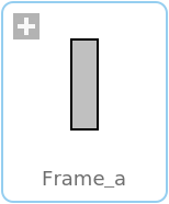
Frame_aCoordinate system fixed to the component with one cut-force and cut-torque (filled rectangular icon) |
|
Wolfram Language
In[1]:=
SystemModel["Modelica.Mechanics.MultiBody.Interfaces.Frame_a"]
Out[1]:=
Information
This information is part of the Modelica Standard Library maintained by the Modelica Association.
Basic definition of a coordinate system that is fixed to a mechanical component. In the origin of the coordinate system the cut-force and the cut-torque is acting. This component has a filled rectangular icon.
Connector Variables (2)
| r_0 |
Causality: None Type: Position[3] (m) Description: Position vector from world frame to the connector frame origin, resolved in world frame |
|---|---|
| R |
Causality: None Type: Orientation Description: Orientation object to rotate the world frame into the connector frame |
Flow Variables (2)
Used in Components (47)
|
Modelica.Mechanics.MultiBody.Examples.Loops.Utilities Cylinder with rod and crank of a combustion engine |
|
|
Modelica.Mechanics.MultiBody.Examples.Loops.Utilities One cylinder with analytic handling of kinematic loop |
|
|
Modelica.Mechanics.MultiBody.Examples.Loops.Utilities V6 engine with analytic loop handling |
|
|
Modelica.Mechanics.MultiBody.Forces.Internal Set force and torque to zero |
|
|
Modelica.Mechanics.MultiBody.Interfaces Adaptor to allow direct connections to the sub-connectors of FlangeWithBearing |
|
|
Modelica.Mechanics.MultiBody.Interfaces Base model for components providing two frame connectors + outer world + assert to guarantee that the component is connected |
|
|
Modelica.Mechanics.MultiBody.Interfaces Base model for components providing two frame connectors + outer world + assert to guarantee that the component is connected (default icon size is factor 2 larger as usual) |
|
|
Modelica.Mechanics.MultiBody.Interfaces Base model for components providing one frame_a connector + outer world + assert to guarantee that the component is connected |
|
|
Modelica.Mechanics.MultiBody.Interfaces Base model for elementary joints (has two frames + outer world + assert to guarantee that the joint is connected) |
|
|
Modelica.Mechanics.MultiBody.Interfaces Base model to measure an absolute frame variable |
|
|
Modelica.Mechanics.MultiBody.Interfaces Base model to measure a relative variable between two frames |
|
|
Modelica.Mechanics.MultiBody.Interfaces Base model for visualizers (has a frame_a on the left side + outer world + assert to guarantee that the component is connected) |
|
|
Modelica.Mechanics.MultiBody.Joints Revolute joint (1 rotational degree-of-freedom, 2 potential states, optional axis flange) |
|
|
Modelica.Mechanics.MultiBody.Joints Revolute joint that is described by 2 positional constraints for usage in a planar loop (the ambiguous cut-force perpendicular to the loop and the ambiguous cut-torques are set arbitrarily to zero) |
|
|
Modelica.Mechanics.MultiBody.Joints Universal - spherical joint aggregation (1 constraint, no potential states) |
|
|
Modelica.Mechanics.MultiBody.Joints Ideal 3-dim. gearbox (arbitrary shaft directions) |
|
|
Modelica.Mechanics.MultiBody.Joints Joint (no mass, no inertia) that describes an ideal rolling wheel (rolling on the plane z=0) |
|
|
Modelica.Mechanics.MultiBody.Joints Joint (no mass, no inertia) that describes an ideal rolling wheel set (two ideal rolling wheels connected together by an axis) |
|
|
Modelica.Mechanics.MultiBody.Joints.Assemblies Universal - prismatic - spherical joint aggregation (no constraints, no potential states) |
|
|
Modelica.Mechanics.MultiBody.Joints.Assemblies Universal - spherical - revolute joint aggregation (no constraints, no potential states) |
|
|
Modelica.Mechanics.MultiBody.Joints.Assemblies Universal - spherical - prismatic joint aggregation (no constraints, no potential states) |
|
|
Modelica.Mechanics.MultiBody.Joints.Assemblies Planar revolute - revolute - revolute joint aggregation (no constraints, no potential states) |
|
|
Modelica.Mechanics.MultiBody.Joints.Assemblies Planar revolute - revolute - prismatic joint aggregation (no constraints, no potential states) |
|
|
RollingConstraintVerticalWheel Modelica.Mechanics.MultiBody.Joints.Internal Rolling constraint for wheel that is always perpendicular to x-y plane |
|
|
Modelica.Mechanics.MultiBody.Joints.Internal Internal model to initialize the angels for Joints.FreeMotionScalarInit |
|
|
Modelica.Mechanics.MultiBody.Parts Fixed translation of frame_b with respect to frame_a |
|
|
Modelica.Mechanics.MultiBody.Parts Fixed translation followed by a fixed rotation of frame_b with respect to frame_a |
|
|
Modelica.Mechanics.MultiBody.Parts Rigid body with mass, inertia tensor and one frame connector (12 potential states) |
|
|
Modelica.Mechanics.MultiBody.Parts Rigid body with mass, inertia tensor, different shapes for animation, and two frame connectors (12 potential states) |
|
|
Modelica.Mechanics.MultiBody.Parts Rigid body with box shape. Mass and animation properties are computed from box data and density (12 potential states) |
|
|
Modelica.Mechanics.MultiBody.Parts Rigid body with cylinder shape. Mass and animation properties are computed from cylinder data and density (12 potential states) |
|
|
Modelica.Mechanics.MultiBody.Parts Rigid body where body rotation and inertia tensor is neglected (6 potential states) |
|
|
Modelica.Mechanics.MultiBody.Parts Propagate 1-dim. support torque to 3-dim. system (provided world.driveTrainMechanics3D=true) |
|
|
Modelica.Mechanics.MultiBody.Parts 1D inertia attachable on 3-dim. bodies (3D dynamic effects are taken into account if world.driveTrainMechanics3D=true) |
|
|
Modelica.Mechanics.MultiBody.Parts.Rotor1D 1D inertia attachable on 3-dim. bodies (3D dynamic effects are taken into account) |
|
|
Modelica.Mechanics.MultiBody.Parts 1D gearbox with arbitrary shaft directions and 3-dim. bearing frame (3D dynamic effects are taken into account provided world.driveTrainMechanics3D=true) |
|
|
Modelica.Mechanics.MultiBody.Parts Ideal rolling wheel on flat surface z=0 (5 positional, 3 velocity degrees of freedom) |
|
|
Modelica.Mechanics.MultiBody.Parts Ideal rolling wheel set consisting of two ideal rolling wheels connected together by an axis |
|
|
Modelica.Mechanics.MultiBody.Sensors Transform absolute vector in to another frame |
|
|
Modelica.Mechanics.MultiBody.Sensors.Internal Base class for absolute sensor models |
|
|
Modelica.Mechanics.MultiBody.Sensors.Internal Base class for absolute sensor models defined by equations (frame_resolve must be connected exactly once) |
|
|
Modelica.Mechanics.MultiBody.Sensors.Internal Base class for relative sensor models |
|
|
Modelica.Mechanics.MultiBody.Sensors.Internal Base class for relative sensor models defined by equations (frame_resolve must be connected exactly once) |
|
|
Modelica.Mechanics.MultiBody.Sensors.Internal Transform absolute vector into another frame |
|
|
Modelica.Mechanics.MultiBody.Sensors.Internal Base class to measure cut force and/or torque between two frames, defined by components |
|
|
Modelica.Mechanics.MultiBody.Sensors.Internal Base class to measure cut force and/or torque between two frames, defined by equations (frame_resolve must be connected exactly once) |
|
|
Modelica.Mechanics.MultiBody.Visualizers Visualizing an elementary shape with dynamically varying shape attributes (has two frame connectors) |