WOLFRAM SYSTEM MODELER
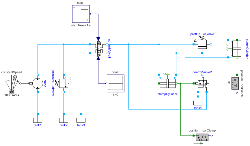
SequenceCircuit1Example circuit with two cylinders working in a sequence |
|
Diagram
Wolfram Language
In[1]:=
SystemModel["Hydraulic.Examples.MultipleActuators.SequenceCircuit1"]
Out[1]:=
Information
This example model shows a sequence of two operations: first a clamping and then a punching operation. A pilot-operated sequence valve is used to trigger the second operation once the clamping cylinder has moved far enough.
Fig. 1 shows how the punching cylinder starts to move when the clamping cylinder has reached a certain position. Fig. 2 shows how the pilot-operated sequence valve starts to move when the mechanically actuated valve has opened.
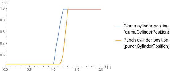
Fig. 1 Cylinder positions
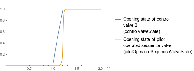
Fig. 2 Opening states of control valve 2 and the pilot-operated sequence valve
Fig. 1 shows how the punching cylinder starts to move when the clamping cylinder has reached a certain position. Fig. 2 shows how the pilot-operated sequence valve starts to move when the mechanically actuated valve has opened.
Fig. 1 Cylinder positions
Fig. 2 Opening states of control valve 2 and the pilot-operated sequence valve
Reference
Industrial Hydraulics Manual, 5th ed., Maumee, OH: Eaton Hydraulics Training Services, 2008 p. 292.Parameters (1)
| medium |
Value: Oil() Type: Medium Description: Medium in the component |
|---|
Components (17)
| medium |
Type: Medium Description: Medium in the component |
|
|---|---|---|
| pilotOperatedSequenceValve |
Type: PilotOperatedSequenceValve Description: Pressure valve, controlled by the pressure at the port_pilot |
|
| controlValve1 |
Type: DCVE43TandemCenter Description: Electrically actuated proportional control valve with four ports and three states |
|
| controlValve2 |
Type: DCVM32 Description: Mechanically actuated proportional valve with three ports and two states |
|
| pressureReliefValve |
Type: PressureReliefValve Description: Pressure valve, controlled by the pressure difference between the ports |
|
| pump |
Type: Pump Description: Model of a pump with fixed displacement and volumes |
|
| constantSpeed |
Type: ConstantSpeed Description: Constant speed, not dependent on torque |
|
| tank1 |
Type: Tank Description: Simple tank with constant pressure |
|
| tank2 |
Type: Tank Description: Simple tank with constant pressure |
|
| tank3 |
Type: Tank Description: Simple tank with constant pressure |
|
| punchCylinder |
Type: CylinderDouble Description: Double cylinder model |
|
| clampCylinder |
Type: CylinderDouble Description: Double cylinder model |
|
| tank4 |
Type: Tank Description: Simple tank with constant pressure |
|
| const |
Type: Constant Description: Generate constant signal of type Real |
|
| step1 |
Type: Step Description: Generate step signal of type Real |
|
| positionSensorPunch |
Type: PositionSensor Description: Ideal sensor to measure the absolute position of flange |
|
| positionSensorClamp |
Type: PositionSensor Description: Ideal sensor to measure the absolute position of flange |