WOLFRAM SYSTEM MODELER
LoadHoldingCircuitExample circuit of a cylinder lifting and holding a mass |
|
Diagram
Wolfram Language
In[1]:=
SystemModel["Hydraulic.Examples.Translation.LoadHoldingCircuit"]
Out[1]:=
Information
This example model shows how to move and hold a load with a cylinder and a counter-balance valve. During lifting, the check valve component of the counter-balance valve allows flow. During lowering, high pressure on the pilot port opens the relief valve component of the counter-balance valve. When the load is not lowered or lifted, the check valve prevents the flow.
Fig. 1 shows how the cylinder is lifted and Fig. 2 shows how the check valve allows flow during the lifting.
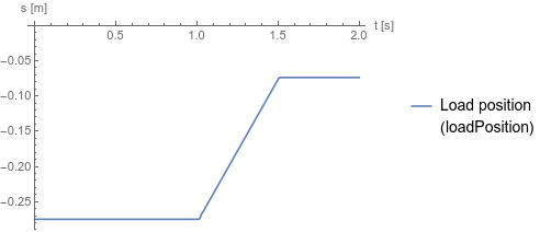
Fig. 1 Load position
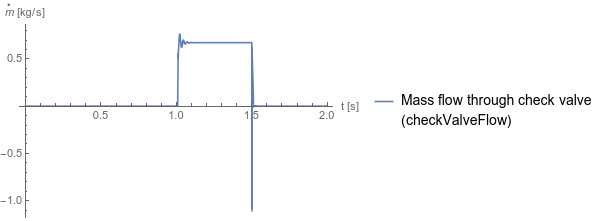
Fig. 2 Flow through the check valve
Fig. 1 shows how the cylinder is lifted and Fig. 2 shows how the check valve allows flow during the lifting.
Fig. 1 Load position
Fig. 2 Flow through the check valve
Reference
Industrial Hydraulics Manual, 5th ed., Maumee, OH: Eaton Hydraulics Training Services, 2008 p. 294.Parameters (1)
| medium |
Value: Oil() Type: Medium Description: Medium in the component |
|---|
Components (17)
| medium |
Type: Medium Description: Medium in the component |
|
|---|---|---|
| tank1 |
Type: Tank Description: Simple tank with constant pressure |
|
| tank2 |
Type: Tank Description: Simple tank with constant pressure |
|
| pump |
Type: Pump Description: Model of a pump with fixed displacement and volumes |
|
| tank3 |
Type: Tank Description: Simple tank with constant pressure |
|
| mass |
Type: Mass Description: Sliding mass with inertia |
|
| positionSensor |
Type: PositionSensor Description: Ideal sensor to measure the absolute position of flange |
|
| cylinderDouble |
Type: CylinderDouble Description: Double cylinder model |
|
| const |
Type: Constant Description: Generate constant signal of type Real |
|
| constantSpeed |
Type: ConstantSpeed Description: Constant speed, not dependent on torque |
|
| pressureReliefValve |
Type: PressureReliefValve Description: Pressure valve, controlled by the pressure difference between the ports |
|
| min1 |
Type: Min Description: Pass through the smallest signal |
|
| stopStep |
Type: Step Description: Generate step signal of type Real |
|
| startStep |
Type: Step Description: Generate step signal of type Real |
|
| controlValve |
Type: PCVE43TandemCenter Description: Electrically actuated proportional control valve with four ports and three states |
|
| gravitationalForce |
Type: ConstantForce Description: Constant force, not dependent on speed |
|
| counterBalanceValve |
Type: CounterBalanceValve Description: Counterbalance valve, allowing flow in one direction. The pilot port can be used to allow flow in the other direction. |