WOLFRAM SYSTEM MODELER
Servo3Example circuit of a cylinder moving a load |
|
Diagram
Wolfram Language
In[1]:=
SystemModel["Hydraulic.Examples.Translation.Servo3"]
Out[1]:=
Information
This example model shows how to move a load with a cylinder. The directional control valve is used to connect the cylinder ends with either the pump or tank depending on the command. The pressure relief valve limits system pressure by opening when the pressure has reached a certain threshold. Pilot-operated check valves are used to reduce slippage.
Fig. 1 shows how the control valve moves to the upper state and then back to its center state. Fig. 2 shows how the check valves allow flow when the control valve is in its upper state. Fig. 3 shows how the cylinder moves when the control valve is in its upper state.
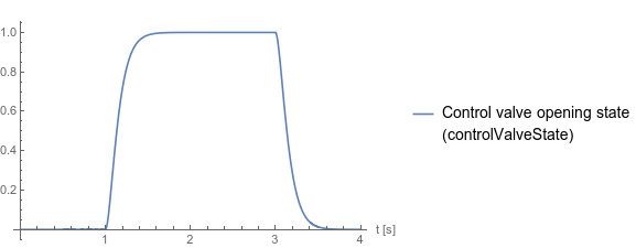
Fig. 1 Control valve opening state
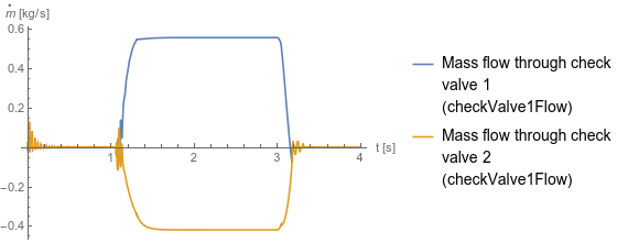
Fig. 2 Flow through check valves. The difference is caused by asymmetric piston areas. The rod diameter to the left of the piston is zero.
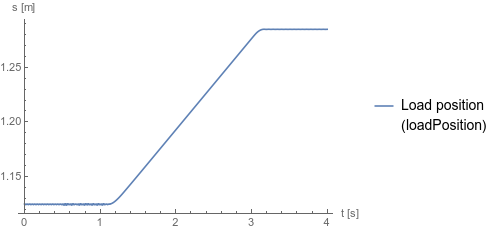
Fig. 3 Load position
Fig. 1 shows how the control valve moves to the upper state and then back to its center state. Fig. 2 shows how the check valves allow flow when the control valve is in its upper state. Fig. 3 shows how the cylinder moves when the control valve is in its upper state.
Fig. 1 Control valve opening state
Fig. 2 Flow through check valves. The difference is caused by asymmetric piston areas. The rod diameter to the left of the piston is zero.
Fig. 3 Load position
Parameters (1)
| medium |
Value: Oil() Type: Medium Description: Medium in the component |
|---|
Components (18)
| medium |
Type: Medium Description: Medium in the component |
|
|---|---|---|
| startStep |
Type: Step Description: Generate step signal of type Real |
|
| tank1 |
Type: Tank Description: Simple tank with constant pressure |
|
| tank2 |
Type: Tank Description: Simple tank with constant pressure |
|
| pump |
Type: Pump Description: Model of a pump with fixed displacement and volumes |
|
| tank3 |
Type: Tank Description: Simple tank with constant pressure |
|
| positionSensor |
Type: PositionSensor Description: Ideal sensor to measure the absolute position of flange |
|
| cylinderDouble |
Type: CylinderDouble Description: Double cylinder model |
|
| constantSpeed |
Type: ConstantSpeed Description: Constant speed, not dependent on torque |
|
| pressureReliefValve |
Type: PressureReliefValve Description: Pressure valve, controlled by the pressure difference between the ports |
|
| controlValve |
Type: PCVE43FloatingCenter Description: Electrically actuated proportional control valve with four ports and three states |
|
| gravity |
Type: ConstantForce Description: Constant force, not dependent on speed |
|
| min |
Type: Min Description: Pass through the smallest signal |
|
| stopStep |
Type: Step Description: Generate step signal of type Real |
|
| const |
Type: Constant Description: Generate constant signal of type Real |
|
| checkValve1 |
Type: PilotOperatedCheckValvePilotToOpen Description: Pilot-operated check valve with lumped volumes |
|
| checkValve2 |
Type: PilotOperatedCheckValvePilotToOpen Description: Pilot-operated check valve with lumped volumes |
|
| mass |
Type: Mass Description: Sliding mass with inertia |