WOLFRAM SYSTEM MODELER
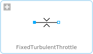
FixedTurbulentThrottleTurbulent restriction |
|
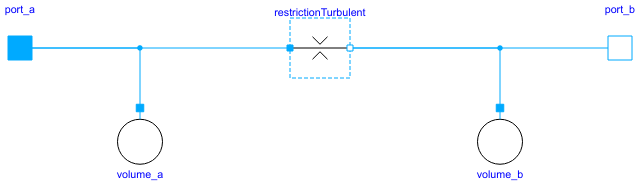
Diagram
Wolfram Language
In[1]:=
SystemModel["Hydraulic.Valves.FlowControl.FixedTurbulentThrottle"]
Out[1]:=
Information
This model with lumped volumes describes turbulent flow. The flow is defined by the equation:
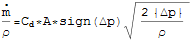
where
where
 | : | Mass flow rate | |
 | : | Fluid density | |
 | : | Discharge coefficient | |
| A | : | Opening area | |
 | : | Pressure difference between ports a and b |
Implementation
The flow equation is linearized for pressure differences near zero to increase numerical stability.Limitations
This model is only valid for turbulent flow. No checks are made if it is physically possible that the flow through the component actually is turbulent.Reference
K. Gieck and R. Gieck, Engineering Formulas, 7th ed., Germering, Germany: Gieck Publishing, 1997 p. N7.Parameters (4)
Connectors (2)
Components (4)
| medium |
Type: Medium Description: Medium in the component |
|
|---|---|---|
| restrictionTurbulent |
Type: RestrictionTurbulent Description: Turbulent restriction |
|
| volume_a |
Type: Volume Description: Fixed volume with fluid storage |
|
| volume_b |
Type: Volume Description: Fixed volume with fluid storage |