WOLFRAM SYSTEM MODELER
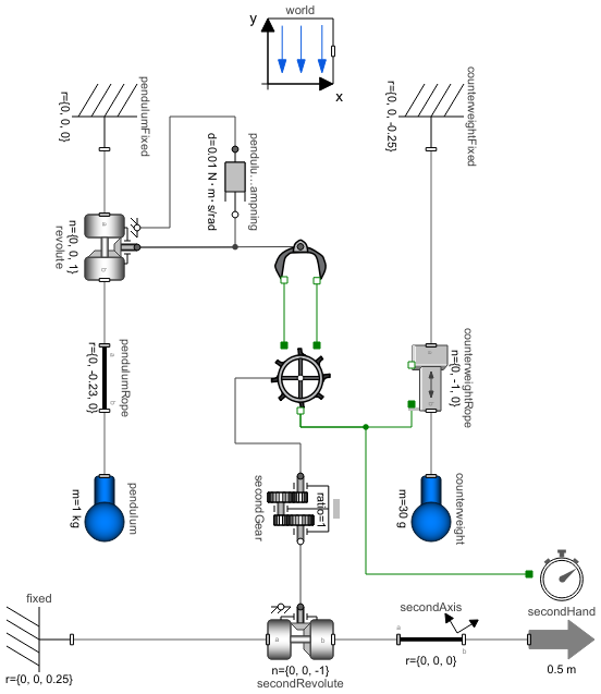
ClockWithOneHandMain pendulum clock example. Clock has one hand that takes one step each second. The movement is controlled by a counterweight. |
|
Diagram
Wolfram Language
In[1]:=
SystemModel["IndustryExamples.ConsumerProducts.PendulumClock.ClockWithOneHand"]
Out[1]:=
Information
This model shows the mechanics of a pendulum clock.
Dynamics
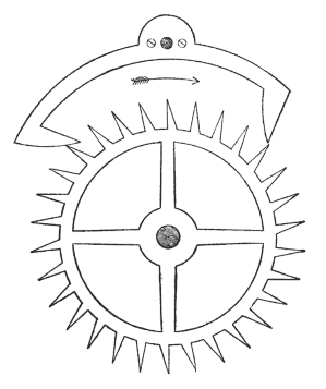
A pendulum clock works by having a pendulum swinging back and forth with a constant period of one second. The pendulum period can be directly determined by the length of the pendulum rod and the gravity affecting the pendulum. The swinging motion pushes on a fork (see graphic), which releases an escapement wheel that is attached to a weight. When the gear is released, gravity pulls the weight down and the gear starts to turn. When the pendulum swings back, the gear is locked once again. The angled cogs and the torque applied to the escapement wheel give the pendulum a small push that returns energy to the pendulum that was lost due to friction.
Plot the Results
Click the Simulate button: 
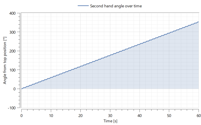
Explore how the hand is rotated during one minute. The secondGear.phi_b variable describes the change in degrees, counting from the start of the simulation. After 60 seconds of simulation, the hand will have rotated 360 degrees.
A plot will automatically be displayed when the simulation has finished. You should see the plot below:
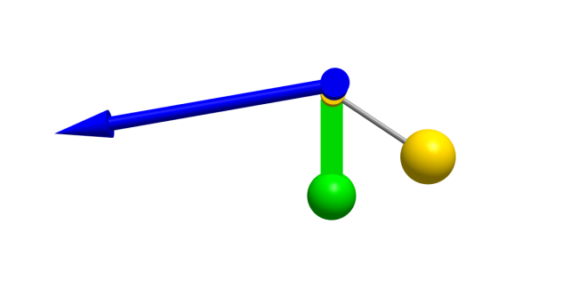
Automatic 3D Animation
Multibody systems have visualizers to show what a real-world system would look like.
To show a 3D animation of the model, follow the steps below:
Click the Simulate button: 
Click the Animation button: 
Use your mouse or trackpad to drag the animation to a good angle and zoom in with your scroll wheel or by using the trackpad. Then click the Play button: 
Expand the Model
Using System Modeler's drag-and-drop functionality, you can expand the model to include a minute hand. First you need to create a new hand. This is done by duplicating the second hand:
- Select the five components shown in the graphic, either by applying Shift+Click to each one individually or selecting them using click-and-drag.
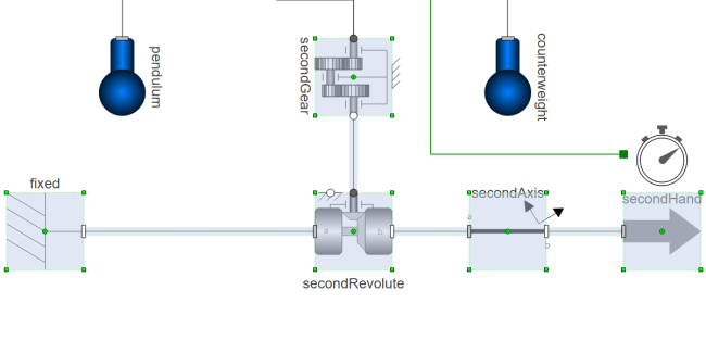
- Press Ctrl+D to duplicate the components.
- Drag the new components toward the bottom of the diagram layer and release them by clicking anywhere on the diagram layer.
Next you need to make the connections to the new hand:
Select the Connection Line Tool button  from the toolbar or press C.
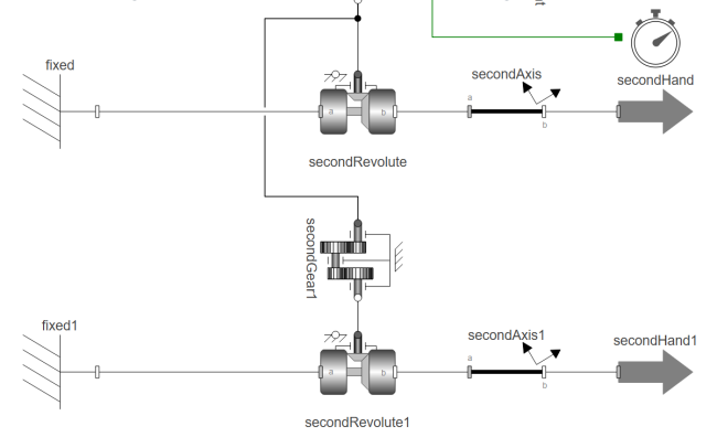
Click the white circle (flange_b) and then click the gray circle on the duplicated gear (flange_a). You can click anywhere in the diagram layer to draw your connection line through that point. Try clicking around the first gear component to get a clean model diagram.
Your diagram should now look something like this:
Now the new hand can be made distinct from the old one:
- Click the duplicated gear. You want the minute hand to turn 1/60 degrees every time the second hand turns one degree. In the General tab, next to the ratio parameter, write 60.
- The duplicated components are now named secondGear1, secondRevolute1, etc. If you want, you can rename them to something more appropriate, like minuteGear, minuteRevolute, and so on. Select each of the duplicated components and press F2. A Component Properties window will show up; in the box next to "Name:", enter your desired component name and click OK.
Repeat the steps in the Simulation section to see the effects of your changes.
Components (17)
| world |
Type: World Description: World coordinate system + gravity field + default animation definition |
|
|---|---|---|
| pendulum |
Type: Body Description: Rigid body with mass, inertia tensor and one frame connector (12 potential states) |
|
| pendulumRope |
Type: FixedTranslation Description: Fixed translation of frame_b with respect to frame_a |
|
| revolute |
Type: Revolute Description: Revolute joint (1 rotational degree-of-freedom, 2 potential states, optional axis flange) |
|
| pendulumFixed |
Type: Fixed Description: Frame fixed in the world frame at a given position |
|
| escapementFork |
Type: EscapementFork Description: Model of escapement fork. |
|
| pendulumDampning |
Type: Damper Description: Linear 1D rotational damper |
|
| escapementWheel |
Type: EscapementWheel Description: Model of clock escapement mechanism. |
|
| counterweight |
Type: Body Description: Rigid body with mass, inertia tensor and one frame connector (12 potential states) |
|
| counterweightRope |
Type: Prismatic Description: Prismatic joint (1 translational degree-of-freedom, 2 potential states, optional axis flange) |
|
| counterweightFixed |
Type: Fixed Description: Frame fixed in the world frame at a given position |
|
| secondGear |
Type: IdealGear Description: Ideal gear without inertia |
|
| fixed |
Type: Fixed Description: Frame fixed in the world frame at a given position |
|
| secondRevolute |
Type: Revolute Description: Revolute joint (1 rotational degree-of-freedom, 2 potential states, optional axis flange) |
|
| secondHand |
Type: FixedArrow Description: Visualizing an arrow with dynamically varying size in frame_a |
|
| secondAxis |
Type: FixedRotation Description: Fixed translation followed by a fixed rotation of frame_b with respect to frame_a |
|
| periodCounter |
Type: PeriodCounter Description: Component used for recording length of pendulum period. |