WOLFRAM SYSTEM MODELER
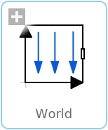
WorldWorld coordinate system + gravity field + default animation definition |
|
Wolfram Language
In[1]:=
SystemModel["Modelica.Mechanics.MultiBody.World"]
Out[1]:=
Information
This information is part of the Modelica Standard Library maintained by the Modelica Association.
Model World represents a global coordinate system fixed in ground. This model serves several purposes:
- It is used as inertial system in which the equations of all elements of the MultiBody library are defined.
- It is the world frame of an animation window in which all elements of the MultiBody library are visualized.
- It is used to define the gravity field in which a multi-body model is present. Default is a uniform gravity field where the gravity acceleration vector g is the same at every position. Additionally, a point gravity field or no gravity can be selected. Also, function gravityAcceleration can be redeclared to a user-defined function that computes the gravity acceleration, see example Examples.Elementary.UserDefinedGravityField.
- It is used to define default settings of animation properties (e.g., the diameter of a sphere representing by default the center of mass of a body, or the diameters of the cylinders representing a revolute joint).
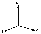
- It is used to define a visual representation of the
world model (= 3 coordinate axes with labels), of the defined
gravity field and of a ground plane perpendicular to the gravity direction.
Since the gravity field function is required from all bodies with mass and the default settings of animation properties are required from nearly every component, exactly one instance of model World needs to be present in every model on the top level. The basic declaration needs to be:
inner Modelica.Mechanics.MultiBody.World world
Note, it must be an inner declaration with instance name world in order that this world object can be accessed from all objects in the model. When dragging the "World" object from the package browser into the diagram layer, this declaration is automatically generated (this is defined via annotations in model World).
All vectors and tensors of a mechanical system are resolved in a frame that is local to the corresponding component. Usually, if all relative joint coordinates vanish, the local frames of all components are parallel to each other, as well as to the world frame (this holds as long as a Parts.FixedRotation, component is not used). In this "reference configuration" it is therefore alternatively possible to resolve all vectors in the world frame, since all frames are parallel to each other. This is often very convenient. In order to give some visual support in such a situation, in the icon of a World instance two axes of the world frame are shown and the labels of these axes can be set via parameters.
Parameters (35)
| enableAnimation |
Value: true Type: Boolean Description: = true, if animation of all components is enabled |
|---|---|
| animateWorld |
Value: true Type: Boolean Description: = true, if world coordinate system shall be visualized |
| animateGravity |
Value: true Type: Boolean Description: = true, if gravity field shall be visualized (acceleration vector or field center) |
| animateGround |
Value: false Type: Boolean Description: = true, if ground plane shall be visualized |
| label1 |
Value: "x" Type: AxisLabel Description: Label of horizontal axis in icon |
| label2 |
Value: "y" Type: AxisLabel Description: Label of vertical axis in icon |
| gravityType |
Value: GravityTypes.UniformGravity Type: GravityTypes Description: Type of gravity field |
| g |
Value: Modelica.Constants.g_n Type: Acceleration (m/s²) Description: Constant gravity acceleration |
| n |
Value: {0, -1, 0} Type: Axis Description: Direction of gravity resolved in world frame (gravity = g*n/length(n)) |
| mu |
Value: 3.986004418e14 Type: Real (m³/s²) Description: Gravity field constant (default = field constant of earth) |
| driveTrainMechanics3D |
Value: true Type: Boolean Description: = true, if 3-dim. mechanical effects of Parts.Mounting1D/Rotor1D/BevelGear1D shall be taken into account |
| axisLength |
Value: nominalLength / 2 Type: Distance (m) Description: Length of world axes arrows |
| axisDiameter |
Value: axisLength / defaultFrameDiameterFraction Type: Distance (m) Description: Diameter of world axes arrows |
| axisShowLabels |
Value: true Type: Boolean Description: = true, if labels shall be shown |
| gravityArrowTail |
Value: {0, 0, 0} Type: Position[3] (m) Description: Position vector from origin of world frame to arrow tail, resolved in world frame |
| gravityArrowLength |
Value: axisLength / 2 Type: Length (m) Description: Length of gravity arrow |
| gravityArrowDiameter |
Value: gravityArrowLength / defaultWidthFraction Type: Diameter (m) Description: Diameter of gravity arrow |
| gravitySphereDiameter |
Value: 12742000 Type: Diameter (m) Description: Diameter of sphere representing gravity center (default = mean diameter of earth) |
| groundAxis_u |
Value: if abs(n[1]) >= 0.99 then {0, 1, 0} else {1, 0, 0} Type: Axis Description: Vector along 1st axis (called u) of ground plane, resolved in world frame (should be perpendicular to gravity direction) |
| groundLength_u |
Value: 2 Type: Length (m) Description: Length of ground plane along groundAxis_u |
| groundLength_v |
Value: groundLength_u Type: Length (m) Description: Length of ground plane perpendicular to groundAxis_u |
| nominalLength |
Value: 1 Type: Length (m) Description: Nominal length of multi-body system |
| defaultAxisLength |
Value: nominalLength / 5 Type: Length (m) Description: Default for length of a frame axis (but not world frame) |
| defaultJointLength |
Value: nominalLength / 10 Type: Length (m) Description: Default for the fixed length of a shape representing a joint |
| defaultJointWidth |
Value: nominalLength / 20 Type: Length (m) Description: Default for the fixed width of a shape representing a joint |
| defaultForceLength |
Value: nominalLength / 10 Type: Length (m) Description: Default for the fixed length of a shape representing a force (e.g., damper) |
| defaultForceWidth |
Value: nominalLength / 20 Type: Length (m) Description: Default for the fixed width of a shape representing a force (e.g., spring, bushing) |
| defaultBodyDiameter |
Value: nominalLength / 9 Type: Length (m) Description: Default for diameter of sphere representing the center of mass of a body |
| defaultWidthFraction |
Value: 20 Type: Real Description: Default for shape width as a fraction of shape length (e.g., for Parts.FixedTranslation) |
| defaultArrowDiameter |
Value: nominalLength / 40 Type: Length (m) Description: Default for arrow diameter (e.g., of forces, torques, sensors) |
| defaultFrameDiameterFraction |
Value: 40 Type: Real Description: Default for arrow diameter of a coordinate system as a fraction of axis length |
| defaultSpecularCoefficient |
Value: 0.7 Type: Real Description: Default reflection of ambient light (= 0: light is completely absorbed) |
| defaultN_to_m |
Value: 1000 Type: Real (N/m) Description: Default scaling of force arrows (length = force/defaultN_to_m) |
| defaultNm_to_m |
Value: 1000 Type: Real (N⋅m/m) Description: Default scaling of torque arrows (length = torque/defaultNm_to_m) |
| gravityAcceleration |
Replaceable Class Redeclared as: standardGravityAcceleration Description: Function to compute the gravity acceleration, resolved in world frame |
Inputs (6)
| axisColor_x |
Default Value: Modelica.Mechanics.MultiBody.Types.Defaults.FrameColor Type: Color Description: Color of x-arrow |
|---|---|
| axisColor_y |
Default Value: axisColor_x Type: Color Description: RGB representation of color |
| axisColor_z |
Default Value: axisColor_x Type: Color Description: Color of z-arrow |
| gravityArrowColor |
Default Value: {0, 230, 0} Type: Color Description: Color of gravity arrow |
| gravitySphereColor |
Default Value: {0, 230, 0} Type: Color Description: Color of gravity sphere |
| groundColor |
Default Value: {200, 200, 200} Type: Color Description: Color of ground plane |
Connectors (1)
| frame_b |
Type: Frame_b Description: Coordinate system fixed in the origin of the world frame |
|---|
Components (13)
| x_arrowLine |
Type: Shape Description: Visualizing an elementary object with variable size; all data have to be set as modifiers (see info layer) |
|
|---|---|---|
| x_arrowHead |
Type: Shape Description: Visualizing an elementary object with variable size; all data have to be set as modifiers (see info layer) |
|
| x_label |
Type: Lines Description: Visualizing a set of lines as cylinders with variable size, e.g., used to display characters (no Frame connector) |
|
| y_arrowLine |
Type: Shape Description: Visualizing an elementary object with variable size; all data have to be set as modifiers (see info layer) |
|
| y_arrowHead |
Type: Shape Description: Visualizing an elementary object with variable size; all data have to be set as modifiers (see info layer) |
|
| y_label |
Type: Lines Description: Visualizing a set of lines as cylinders with variable size, e.g., used to display characters (no Frame connector) |
|
| z_arrowLine |
Type: Shape Description: Visualizing an elementary object with variable size; all data have to be set as modifiers (see info layer) |
|
| z_arrowHead |
Type: Shape Description: Visualizing an elementary object with variable size; all data have to be set as modifiers (see info layer) |
|
| z_label |
Type: Lines Description: Visualizing a set of lines as cylinders with variable size, e.g., used to display characters (no Frame connector) |
|
| gravityArrowLine |
Type: Shape Description: Visualizing an elementary object with variable size; all data have to be set as modifiers (see info layer) |
|
| gravityArrowHead |
Type: Shape Description: Visualizing an elementary object with variable size; all data have to be set as modifiers (see info layer) |
|
| gravitySphere |
Type: Shape Description: Visualizing an elementary object with variable size; all data have to be set as modifiers (see info layer) |
|
| surface |
Type: Surface Description: Visualizing a moveable, parameterized surface; the surface characteristic is provided by a function |
Used in Examples (36)
|
Modelica.Mechanics.MultiBody.Examples.Elementary Simple double pendulum with two revolute joints and two bodies |
|
|
Modelica.Mechanics.MultiBody.Examples.Elementary Demonstrate how to initialize a double pendulum so that its tip starts at a predefined position |
|
|
Modelica.Mechanics.MultiBody.Examples.Elementary Demonstrate usage of ForceAndTorque element |
|
|
Modelica.Mechanics.MultiBody.Examples.Elementary Free flying body attached by two springs to environment |
|
|
Modelica.Mechanics.MultiBody.Examples.Elementary Determine spring constant such that system is in steady state at given position |
|
|
Modelica.Mechanics.MultiBody.Examples.Elementary Demonstrate line force with two point masses using a JointUPS and alternatively a LineForceWithTwoMasses component |
|
|
Modelica.Mechanics.MultiBody.Examples.Elementary Simple pendulum with one revolute joint and one body |
|
|
Modelica.Mechanics.MultiBody.Examples.Elementary Simple spring/damper/mass system |
|
|
Modelica.Mechanics.MultiBody.Examples.Elementary Two point masses in a point gravity field |
|
|
Modelica.Mechanics.MultiBody.Examples.Elementary Two point masses in a point gravity field (rotation of bodies is neglected) |
|
|
Modelica.Mechanics.MultiBody.Examples.Elementary Rigidly connected point masses in a point gravity field |
|
|
Modelica.Mechanics.MultiBody.Examples.Elementary Simple spring/damper/mass system |
|
|
Modelica.Mechanics.MultiBody.Examples.Elementary Mass attached with a spring to the world frame |
|
|
Modelica.Mechanics.MultiBody.Examples.Elementary Point mass hanging on a spring |
|
|
Modelica.Mechanics.MultiBody.Examples.Elementary 3-dim. springs in series and parallel connection |
|
|
Modelica.Mechanics.MultiBody.Examples.Elementary Single wheel rolling on ground starting from an initial speed |
|
|
Modelica.Mechanics.MultiBody.Examples.Elementary Rolling wheel set that is driven by torques driving the wheels |
|
|
Modelica.Mechanics.MultiBody.Examples.Elementary Rolling wheel set that is pulled by a force |
|
|
Modelica.Mechanics.MultiBody.Examples.Elementary Demonstrate the modeling of heat losses |
|
|
Modelica.Mechanics.MultiBody.Examples.Elementary Demonstrate the modeling of a user-defined gravity field |
|
|
Modelica.Mechanics.MultiBody.Examples.Loops V6 engine with 6 cylinders, 6 planar loops and 1 degree-of-freedom |
|
|
Modelica.Mechanics.MultiBody.Examples.Loops V6 engine with 6 cylinders, 6 planar loops, 1 degree-of-freedom and analytic handling of kinematic loops |
|
|
Modelica.Mechanics.MultiBody.Examples.Loops One kinematic loop with four bars (with only revolute joints; 5 non-linear equations) |
|
|
Modelica.Mechanics.MultiBody.Examples.Loops One kinematic loop with four bars (with UniversalSpherical joint; 1 non-linear equation) |
|
|
Modelica.Mechanics.MultiBody.Examples.Loops One kinematic loop with four bars (with JointSSP joint; analytic solution of non-linear algebraic loop) |
|
|
Modelica.Mechanics.MultiBody.Examples.Loops Planar four bars mechanism with one kinematic loop (with RevolutePlanarLoopConstraint joint) |
|
|
Modelica.Mechanics.MultiBody.Examples.Loops Mechanism with three planar kinematic loops and one degree-of-freedom with analytic loop handling (with JointRRR joints) |
|
|
Modelica.Mechanics.MultiBody.Examples.Rotational3DEffects Demonstrates that a cylindrical body can be replaced by Rotor1D model |
|
|
Modelica.Mechanics.MultiBody.Examples.Rotational3DEffects Demonstrates usage of models Rotor1D and Mounting1D |
|
|
Modelica.Mechanics.MultiBody.Examples.Rotational3DEffects Demonstrates usage of model Rotor1D mounted on a moving body |
|
|
Modelica.Mechanics.MultiBody.Examples.Rotational3DEffects Demonstrate usage of GearConstraint model |
|
|
Modelica.Mechanics.MultiBody.Examples.Rotational3DEffects Demonstrates the usage of a BevelGear1D model and how to calculate the power of such an element |
|
|
Modelica.Mechanics.MultiBody.Examples.Constraints Body attached by one spring and two prismatic joints or constrained to environment |
|
|
Modelica.Mechanics.MultiBody.Examples.Constraints Body attached by one spring and revolute joint or constrained to environment |
|
|
Modelica.Mechanics.MultiBody.Examples.Constraints Body attached by one spring and spherical joint or constrained to environment |
|
|
Modelica.Mechanics.MultiBody.Examples.Constraints Body attached by one spring and universal joint or constrained to environment |
Used in Components (31)
|
Modelica.Mechanics.MultiBody.Examples.Loops.Utilities Base model for one cylinder engine |
|
|
Modelica.Mechanics.MultiBody.Examples.Systems.RobotR3.Utilities Model of the mechanical part of the r3 robot (without animation) |
|
|
Modelica.Mechanics.MultiBody.Interfaces Base model for components providing two frame connectors + outer world + assert to guarantee that the component is connected |
|
|
Modelica.Mechanics.MultiBody.Interfaces Base model for components providing two frame connectors + outer world + assert to guarantee that the component is connected (default icon size is factor 2 larger as usual) |
|
|
Modelica.Mechanics.MultiBody.Interfaces Base model for components providing one frame_a connector + outer world + assert to guarantee that the component is connected |
|
|
Modelica.Mechanics.MultiBody.Interfaces Base model for components providing one frame_b connector + outer world + assert to guarantee that the component is connected |
|
|
Modelica.Mechanics.MultiBody.Interfaces Base model for elementary joints (has two frames + outer world + assert to guarantee that the joint is connected) |
|
|
Modelica.Mechanics.MultiBody.Interfaces Base model to measure an absolute frame variable |
|
|
Modelica.Mechanics.MultiBody.Interfaces Base model to measure a relative variable between two frames |
|
|
Modelica.Mechanics.MultiBody.Interfaces Base model for visualizers (has a frame_a on the left side + outer world + assert to guarantee that the component is connected) |
|
|
Modelica.Mechanics.MultiBody.Joints Revolute joint (1 rotational degree-of-freedom, 2 potential states, optional axis flange) |
|
|
Modelica.Mechanics.MultiBody.Joints Revolute joint that is described by 2 positional constraints for usage in a planar loop (the ambiguous cut-force perpendicular to the loop and the ambiguous cut-torques are set arbitrarily to zero) |
|
|
Modelica.Mechanics.MultiBody.Parts Frame fixed in the world frame at a given position |
|
|
Modelica.Mechanics.MultiBody.Parts Fixed translation of frame_b with respect to frame_a |
|
|
Modelica.Mechanics.MultiBody.Parts Fixed translation followed by a fixed rotation of frame_b with respect to frame_a |
|
|
Modelica.Mechanics.MultiBody.Parts Rigid body with mass, inertia tensor and one frame connector (12 potential states) |
|
|
Modelica.Mechanics.MultiBody.Parts Rigid body with mass, inertia tensor, different shapes for animation, and two frame connectors (12 potential states) |
|
|
Modelica.Mechanics.MultiBody.Parts Rigid body with box shape. Mass and animation properties are computed from box data and density (12 potential states) |
|
|
Modelica.Mechanics.MultiBody.Parts Rigid body with cylinder shape. Mass and animation properties are computed from cylinder data and density (12 potential states) |
|
|
Modelica.Mechanics.MultiBody.Parts Rigid body where body rotation and inertia tensor is neglected (6 potential states) |
|
|
Modelica.Mechanics.MultiBody.Parts Propagate 1-dim. support torque to 3-dim. system (provided world.driveTrainMechanics3D=true) |
|
|
Modelica.Mechanics.MultiBody.Parts 1D inertia attachable on 3-dim. bodies (3D dynamic effects are taken into account if world.driveTrainMechanics3D=true) |
|
|
Modelica.Mechanics.MultiBody.Parts.Rotor1D 1D inertia attachable on 3-dim. bodies (3D dynamic effects are taken into account) |
|
|
Modelica.Mechanics.MultiBody.Parts 1D gearbox with arbitrary shaft directions and 3-dim. bearing frame (3D dynamic effects are taken into account provided world.driveTrainMechanics3D=true) |
|
|
Modelica.Mechanics.MultiBody.Sensors Measure absolute kinematic quantities of frame connector |
|
|
Modelica.Mechanics.MultiBody.Sensors Measure relative kinematic quantities between two frame connectors |
|
|
Modelica.Mechanics.MultiBody.Sensors.Internal Base class to measure cut force and/or torque between two frames, defined by components |
|
|
Modelica.Mechanics.MultiBody.Sensors.Internal Base class to measure cut force and/or torque between two frames, defined by equations (frame_resolve must be connected exactly once) |
|
|
Modelica.Mechanics.MultiBody.Visualizers Visualizing an elementary shape with dynamically varying shape attributes (has two frame connectors) |
|
|
Modelica.Mechanics.MultiBody.Visualizers.Advanced Visualizing an arrow with variable size |
|
|
Modelica.Mechanics.MultiBody.Visualizers.Advanced Visualizing a double arrow with variable size |