WOLFRAM SYSTEMMODELER
StiffServoMechanismA servo mechanism with a stiff axis |
|
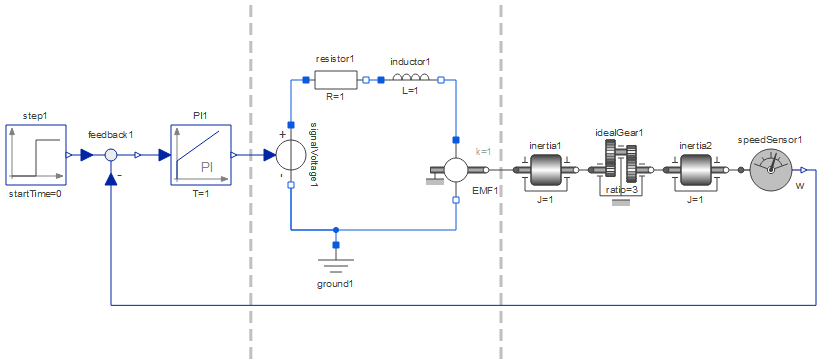
Diagram
Wolfram Language
In[1]:=

SystemModel["IntroductoryExamples.MultiDomain.StiffServoMechanism"]
Out[1]:=
Information
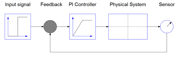
The structure of the control system is shown in the schematic picture below. It consists of an input signal, a sensor, a feedback loop, and a regulator. The physical system consists of the gear and axis system described in DC Motor and Weak Axis. Since the physical system has negative static gain the PI gain also has to be negative.
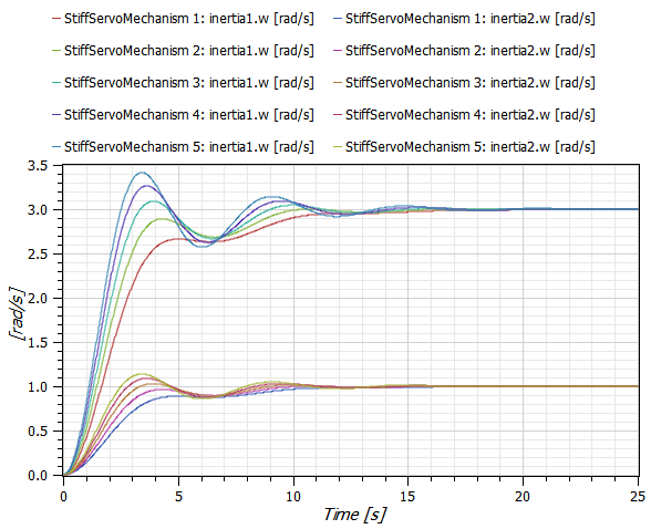
By varying the controller gain k we can study how the system response is affected. In this case we vary the gain from 1 (StiffServoMechanism 1) to 2 (StiffServoMechanism 5) in steps of 0.25. The plot below shows the result:
For a step by step tutorial see Multidomain—A Servo Mechanism.
Components (12)
| idealGear1 |
Type: IdealGear Description: |
|
|---|---|---|
| inertia1 |
Type: Inertia Description: |
|
| inductor1 |
Type: Inductor Description: |
|
| ground1 |
Type: Ground Description: |
|
| inertia2 |
Type: Inertia Description: |
|
| feedback1 |
Type: Feedback Description: |
|
| speedSensor1 |
Type: SpeedSensor Description: |
|
| signalVoltage1 |
Type: SignalVoltage Description: |
|
| PI1 |
Type: PI Description: |
|
| resistor1 |
Type: Resistor Description: |
|
| EMF1 |
Type: EMF Description: |
|
| step1 |
Type: Step Description: |