WOLFRAM SYSTEM MODELER
PID_ControllerDemonstrates the usage of a Continuous.LimPID controller |
|
Diagram
Wolfram Language
In[1]:=
SystemModel["Modelica.Blocks.Examples.PID_Controller"]
Out[1]:=
Information
This information is part of the Modelica Standard Library maintained by the Modelica Association.
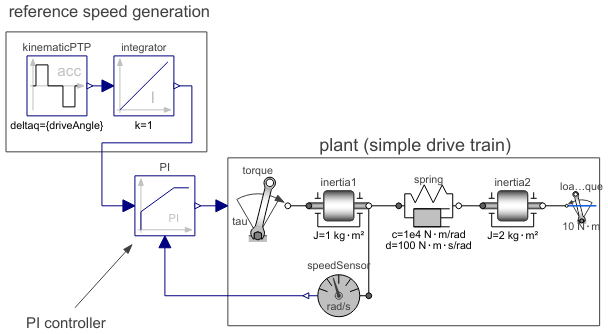
This is a simple drive train controlled by a PID controller:
- The two blocks "kinematic_PTP" and "integrator" are used to generate the reference speed (= constant acceleration phase, constant speed phase, constant deceleration phase until inertia is at rest). To check whether the system starts in steady state, the reference speed is zero until time = 0.5 s and then follows the sketched trajectory.
- The block "PI" is an instance of "Blocks.Continuous.LimPID" which is a PID controller where several practical important aspects, such as anti-windup-compensation has been added. In this case, the control block is used as PI controller.
- The output of the controller is a torque that drives a motor inertia "inertia1". Via a compliant spring/damper component, the load inertia "inertia2" is attached. A constant external torque of 10 Nm is acting on the load inertia.
The PI controller is initialized in steady state (initType=SteadyState) and the drive shall also be initialized in steady state. However, it is not possible to initialize "inertia1" in SteadyState, because "der(inertia1.phi)=inertia1.w=0" is an input to the PI controller that defines that the derivative of the integrator state is zero (= the same condition that was already defined by option SteadyState of the PI controller). Furthermore, one initial condition is missing, because the absolute position of inertia1 or inertia2 is not defined. The solution shown in this examples is to initialize the angle and the angular acceleration of "inertia1".
In the following figure, results of a typical simulation are shown:
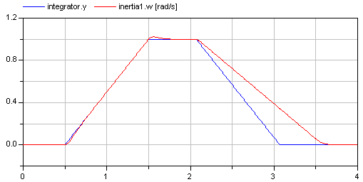
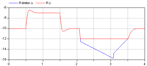
In the upper figure the reference speed (= integrator.y) and the actual speed (= inertia1.w) are shown. As can be seen, the system initializes in steady state, since no transients are present. The inertia follows the reference speed quite good until the end of the constant speed phase. Then there is a deviation. In the lower figure the reason can be seen: The output of the controller (PI.y) is in its limits. The anti-windup compensation works reasonably, since the input to the limiter (PI.limiter.u) is forced back to its limit after a transient phase.
Parameters (1)
| driveAngle |
Value: 1.570796326794897 Type: Angle (rad) Description: Reference distance to move |
|---|
Components (9)
| PI |
Type: LimPID Description: P, PI, PD, and PID controller with limited output, anti-windup compensation, setpoint weighting and optional feed-forward |
|
|---|---|---|
| inertia1 |
Type: Inertia Description: 1D-rotational component with inertia |
|
| torque |
Type: Torque Description: Input signal acting as external torque on a flange |
|
| spring |
Type: SpringDamper Description: Linear 1D rotational spring and damper in parallel |
|
| inertia2 |
Type: Inertia Description: 1D-rotational component with inertia |
|
| kinematicPTP |
Type: KinematicPTP Description: Move as fast as possible along a distance within given kinematic constraints |
|
| integrator |
Type: Integrator Description: Output the integral of the input signal with optional reset |
|
| speedSensor |
Type: SpeedSensor Description: Ideal sensor to measure the absolute angular velocity of flange |
|
| loadTorque |
Type: ConstantTorque Description: Constant torque, not dependent on speed |