WOLFRAM SYSTEM MODELER
ProfileShiftAnalyzing the clearance between gears |
|
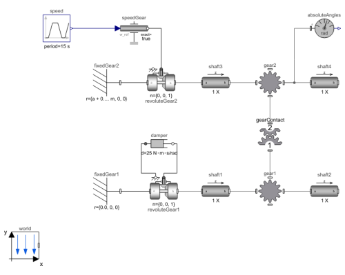
Diagram
Wolfram Language
SystemModel["RotatingMachinery.Examples.Gears.SpurGears.ProfileShift"]

Information
Profile Shifting of Gears
In this example, a gear with profile shifting is compared to one without it.
The profile shift is the displacement of the manufacturing rack datum line (pitch circle) from the reference circle. Profile shifts are used and/or needed to adjust clearance in gearboxes but also to optimize gear strength, as shown in Figure 1.
Figure 1: Gear teeth.
Figure 2 displays a gear train consisting of two gearwheels with a clearance. The clearence is dependent on positioning and profile shift. If the gap is too large between the two gears, the teeth will not be close enough to be in contact.
Figure 1: Gear train.
Figure 3 displays three gears with the same number of teeth (z = 20, alpha0 = 20°, the involute angle of the teeth) but with three different profile shift factors (1.2, -0.2, and 0.5), all within the profile shift factor range between 1.2 and -0.2. Positive profile shifts increase the bending strength of the gear, while negative shifts reduce the center distance slightly when a few mm clearance is needed. In this example, one gear with a profile shift of 0.2 is compared to a non-profile–shifted gear.
Figure 3: Gear teeth.
This example can be used to experiment with profile shift of the gears, i.e. the variables x1 and x2. The backlash is the play between the teeth when two gears are meshed and is needed for the smooth rotation of gears. When the backlash is too large, it leads to increased vibration and noise, while a backlash that is too small leads to tooth failure due to the lack of lubrication.
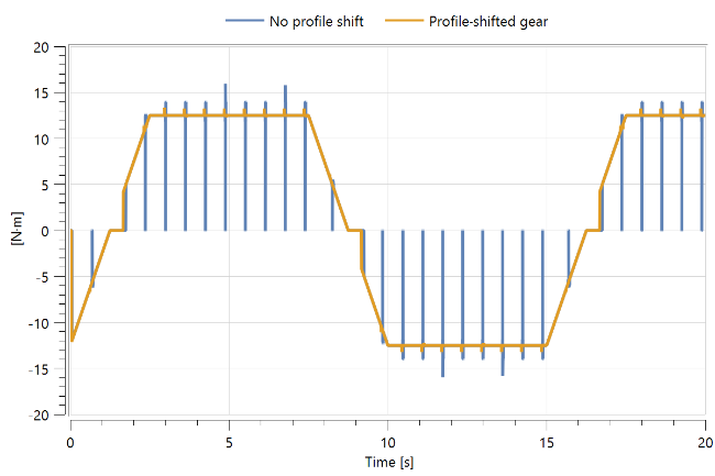
Figure 4 compares two gears, one profile-shifted (x1 = x2 = 0.2) and one regular.

Figure 4: Profile-shifted vs. regular gear torque transmissions.
As seen in the figure, there are periodic zero torque transmissions because of the backlash in no profile shift gear. Such behavior is the reason for noisy gear machinery, which needs to be avoided.
For more information about gear geometry and parameters, see [1].
References
[1] Dahl, M., H. Wettergren, and H. Tidefelt. "Modelica Spur Gears with Hertzian Contact Forces." Proceedings of the 12th International Modelica Conference, Prague, Czech Republic, May 15–17, 2017. Linköping Electronic Conference Proceedings 132, no. 82 (2017): 755–763. http://dx.doi.org/10.3384/ecp17132755).
Parameters (7)
| m |
Value: 0.005 Type: Module (m) Description: Gear module |
|---|---|
| a |
Value: (m * z1 + m * z2) / 2 Type: Distance (m) Description: Distance from wheel center 1 to wheel center 2 |
| alpha0 |
Value: 20 * Modelica.Constants.pi / 180 Type: Angle (rad) Description: Reference profile angle |
| z1 |
Value: 20 Type: Integer Description: Number of teeth in wheel one |
| z2 |
Value: 20 Type: Integer Description: Number of teeth in wheel two |
| x1 |
Value: 1e-02 Type: Real Description: Profile shift for gear wheel one |
| x2 |
Value: 0 Type: Real Description: Profile shift for gear wheel two |
Components (16)
| world |
Type: World Description: World coordinate system + gravity field + default animation definition |
|
|---|---|---|
| fixedGear1 |
Type: Fixed Description: Frame fixed in the world frame at a given position |
|
| revoluteGear1 |
Type: Revolute Description: Revolute joint (1 rotational degree-of-freedom, 2 potential states, optional axis flange) |
|
| speedGear |
Type: Speed Description: Forced movement of a flange according to a reference angular velocity signal |
|
| gear1 |
Type: SpurGear Description: Spur gear with mass, rotations and visualization |
|
| revoluteGear2 |
Type: Revolute Description: Revolute joint (1 rotational degree-of-freedom, 2 potential states, optional axis flange) |
|
| fixedGear2 |
Type: Fixed Description: Frame fixed in the world frame at a given position |
|
| gear2 |
Type: SpurGear Description: Spur gear with mass, rotations and visualization |
|
| gearContact |
Type: GearForceCalculation Description: Class calculating gear mesh contact forces |
|
| damper |
Type: Damper Description: Linear 1D rotational damper |
|
| absoluteAngles |
Type: AbsoluteAngles Description: Measure absolute angles between frame connector and the world frame |
|
| shaft4 |
Type: CylindricalBeam Description: Class with a flexible cylindrical beam |
|
| shaft3 |
Type: CylindricalBeam Description: Class with a flexible cylindrical beam |
|
| shaft1 |
Type: CylindricalBeam Description: Class with a flexible cylindrical beam |
|
| shaft2 |
Type: CylindricalBeam Description: Class with a flexible cylindrical beam |
|
| speed |
Type: Trapezoid Description: Generate trapezoidal signal of type Real |

