WOLFRAM SYSTEM MODELER
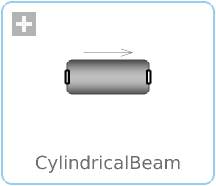
CylindricalBeamClass with a flexible cylindrical beam |
|
Diagram

Wolfram Language
In[1]:=
SystemModel["RotatingMachinery.Shafts.CylindricalBeam"]
Out[1]:=
Information
Shaft
The shafts in the Rotating Machinery library are flexible, meaning they deflect under applied loads and have a high level of accuracy. This CylindricalBeam top-layer model is built up by "n" number of elements, where the elements consist of Cylindrical Beams. These beams are an extended version of the Euler–Bernoulli Beam element.
In addition to the Euler–Bernoulli Beam element, axial and twisting deformation is also taken into account. Increasing the number of beam elements ("n") will increase the physical accuracy of the model, at the cost of more computation time.
To see more details of how this component has been implemented, see the documentation of the CylindricalBeamSegment.
When a shaft is connected to multiple supports, the system becomes overdetermined, and the solution depends on the specific constraints chosen. To ensure the desired results, the enforceStates_b parameter should be set accordingly. If it is connected to a support, it should be set to false. As a rule of thumb, enforceStates_a is false for all elements and enforceStates_b is true for all elements until it is rooted, i.e. normally the last element.
More examples; RotatingMachinery.Examples.Shafts.
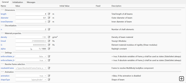
Figure 1: Shaft parameters tab.
To accurately calculate the orientation of each segmented piece of a beam as it deflects, it is necessary to continuously evaluate the orientation. However, when working with a generic flexible beam, constraints can affect the calculation of the orientation. The resolveInFrame parameter allows users to choose how the orientation is calculated. The default value for this parameter is typically sufficient. However, if the model is built from left to right (from frame_a to frame_b), this value may need to be changed to frame_b if the beam is only connected in frame_b.
Note that the length direction is fixed to orientation of {0,0,1}, i.e. z direction.
References
[1] Adams, M. L . Rotating Machinery Vibration: From Analysis to Troubleshooting (2nd ed.). CRC Press, 2010.
Parameters (28)
| length |
Type: Length (m) Description: Total length of all beams |
|---|---|
| diameter |
Type: Diameter (m) Description: Outer diameter of beam |
| innerDiameter |
Value: 0 Type: Diameter (m) Description: Inner diameter of beam |
| n |
Value: 1 Type: Integer Description: Number of shaft elements |
| density |
Value: 7850 Type: Density (kg/m³) Description: Density of beam material |
| Emod |
Value: 210000000000.0 Type: ModulusOfElasticity (Pa) Description: Young's Modulus |
| G |
Value: 80000000000.0 Type: ShearModulus (Pa) Description: Element material modulus of rigidity (Shear modulus) |
| alpha |
Value: 1 / 1000 Type: Real Description: Rayleigh constant |
| enforceStates_a |
Value: false Type: Boolean Description: = true, if absolute variables of frame_a shall be used as states (StateSelect.always) |
| enforceStates_b |
Value: true Type: Boolean Description: = true, if absolute variables of frame_b shall be used as states (StateSelect.always) |
| animation |
Value: true Type: Boolean Description: =false, if the animation is disabled |
| shapeType |
Value: "pipecylinder" Type: ShapeType Description: Shape of beam |
| r_a_Fixed |
Value: false Type: Boolean Description: = true, if theta_a_start are used as initial values, else as guess values |
| r_a_start |
Value: {0, 0, 0} Type: Position[3] (m) Description: Initial values of position |
| r_b_Fixed |
Value: false Type: Boolean Description: = true, if theta_b_start are used as initial values, else as guess values |
| r_b_start |
Value: {0, 0, 0} Type: Position[3] (m) Description: Initial values of position |
| v_a_Fixed |
Value: false Type: Boolean Description: = true, if v_a_start are used as initial values, else as guess values |
| v_a_start |
Value: {0, 0, 0} Type: Velocity[3] (m/s) Description: Initial values of velocity |
| v_b_Fixed |
Value: false Type: Boolean Description: = true, if v_b_start are used as initial values, else as guess values |
| v_b_start |
Value: {0, 0, 0} Type: Velocity[3] (m/s) Description: Initial values of velocity |
| theta_a_Fixed |
Value: false Type: Boolean Description: = true, if theta_a_start are used as initial values, else as guess values |
| theta_a_start |
Value: {0, 0, 0} Type: Angle[3] (rad) Description: Initial values of angles |
| theta_b_Fixed |
Value: false Type: Boolean Description: = true, if theta_b_start are used as initial values, else as guess values |
| theta_b_start |
Value: {0, 0, 0} Type: Angle[3] (rad) Description: Initial values of angles |
| thetad_a_Fixed |
Value: false Type: Boolean Description: = true, if der(theta_a_start) are used as initial values, else as guess values |
| thetad_a_start |
Value: {0, 0, 0} Type: AngularVelocity[3] (rad/s) Description: Initial values of angles |
| thetad_b_Fixed |
Value: false Type: Boolean Description: = true, if der(theta_b_start) are used as initial values, else as guess values |
| thetad_b_start |
Value: {0, 0, 0} Type: AngularVelocity[3] (rad/s) Description: Initial values of angles |
Connectors (2)
Components (2)
| cylindricalBeam |
Type: CylindricalBeamSegment[n] Description: Class with a flexible cylindrical beam |
|
|---|---|---|
| world |
Type: World Description: World coordinate system + gravity field + default animation definition |
Used in Examples (24)
|
RotatingMachinery.Examples.BearingAnalysis Comparison of a defect and regular bearing |
|
|
RotatingMachinery.Examples.BearingAnalysis Two roller bearings' responses under a loaded shaft |
|
|
RotatingMachinery.Examples.BearingAnalysis Two roller bearings on flexible supports |
|
|
RotatingMachinery.Examples.BearingAnalysis Frequency analysis of a bearing defect on a simple shaft mounted on a structure |
|
|
RotatingMachinery.Examples.StabilityAnalysis Finding whirling frequencies of a rotating shaft: Part I |
|
|
RotatingMachinery.Examples.StabilityAnalysis Finding whirling frequencies of a rotating shaft: Part II |
|
|
RotatingMachinery.Examples.Gears.SpurGears Building a two-wheeled gear train on shafts |
|
|
RotatingMachinery.Examples.Gears.SpurGears Analyzing the clearance between gears |
|
|
RotatingMachinery.Examples.Gears.SpurGears Construction of triple gearbox on three shafts |
|
|
RotatingMachinery.Examples.Gears.SpurGears Application of a driven internal gearwheel |
|
|
RotatingMachinery.Examples.Gears.SpurGears Study of a driving internal gear |
|
|
RotatingMachinery.Examples.Gears.PlanetaryGears Building a three-shaft gearbox; WindTurbine Part II |
|
|
RotatingMachinery.Examples.Gears.PlanetaryGears Assembly of a planetary gear and a three-shafted gearbox; Part I and Part II |
|
|
RotatingMachinery.Examples.JeffcottRotorDamping Determine shaft damping |
|
|
RotatingMachinery.Examples.JeffcottRotorDamping A basic Jeffcott rotor with internal and external damping |
|
|
RotatingMachinery.Examples.RotorBalancing An unbalanced rotor stabilized by balancing planes |
|
|
RotatingMachinery.Examples.ContactAnalysis Study of contact forces between a disk and a housing |
|
|
RotatingMachinery.Examples.ContactAnalysis Study of a running up clamped free rotor |
|
|
RotatingMachinery.Examples.ContactAnalysis Inspection of deflection of a free rotor without clearance |
|
|
RotatingMachinery.Examples.ContactAnalysis Calculation of deflection for a rotor with a surrounding and a clearance |
|
|
RotatingMachinery.Examples.ContactAnalysis Application of a running down rotor deflection with a clearance |
|
|
RotatingMachinery.Examples.Shafts Study of a cantilever beam |
|
|
RotatingMachinery.Examples.Shafts Inspection of an axle's vibrations |
|
|
RotatingMachinery.Examples.Shafts Inspection of a car axle deflection on tires |
Used in Components (2)
|
RotatingMachinery.Gears.PlanetaryGears This component is a three-shaft gearbox and is a part of the wind turbine gearbox |
|
|
RotatingMachinery.Gears.PlanetaryGears Class containing a basic planetary gear model |