WOLFRAM SYSTEM MODELER
ClampedRotorStudy of contact forces between a disk and a housing |
|
Diagram
Wolfram Language
In[1]:=
SystemModel["RotatingMachinery.Examples.ContactAnalysis.ClampedRotor"]
Out[1]:=
Information
Studying Clamped Rotor Contact Forces
This example shows how to model and study contact forces of a clamped rotor.
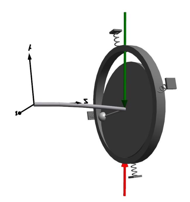 Figure 1: Clamped rotor with a disk and a housing.
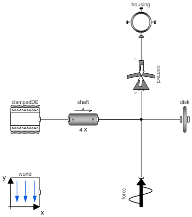
A clamped rotor with a housing is shown in Figure 1. It is modeled by connecting a shaft to a clamped support at one end and then a disk at the other end. The model includes a housing and a contact component, representing the interaction dynamics between the disk and housing; see Figure 2.
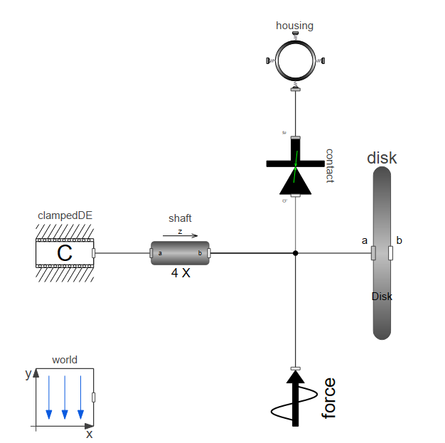 Figure 2: Clamped rotor model diagram.
The support clampedDE enables rotation only around the shaft axis (z axis). Depending on the parameter settings, the support will act as a clamped support with a built-in fixed point or a clamped support that connects to another frame (activated by setting useFlangeSupport to true). The default setting is a clamped support with a built-in fixed point.
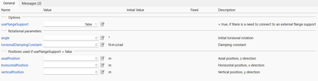 Figure 2: Clamped support parameters tab.
The disk component parameters are given in Figure 3. It is possible to model a disk including a mass unbalance by setting Unbalance parameters, i.e. size of the unbalance and position in the radial direction. In this example, a 0.3 kg.m unbalance is added in both directions.
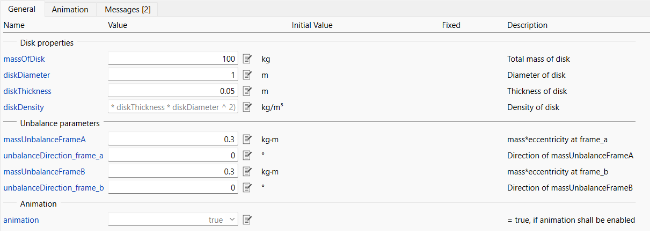 Figure 3: Disk parameters tab.
The housing acts as a housing support. It gets as stiff or as flexible as specified in Structural constants.
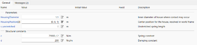 Figure 4: Housing parameters tab.
The interaction force dynamics is modeled by a contact component, which calculates normal and friction contact forces between the disk and the housing. The forces are zero until the deflection is larger than the parameter gapShaftHousing see Figure 5. The stiffness and damping coefficients for the contact force in the normal direction are set by kInSurface and damping. The friction coefficient has a static and a dynamic part that specifies the magnitude of horizontal forces. In this case, they are not of interest and therefore set to 0.
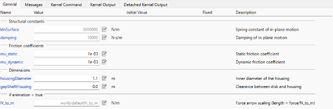 Figure 5: Contact parameters tab.
A force is applied to the disk. After 10 seconds, the applied force starts to rotate, which causes the contact force to change in response to this. The disk deflection over time is plotted in Figure 6.
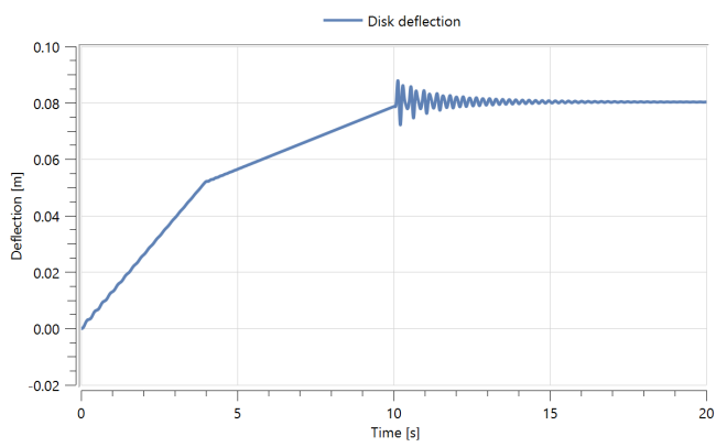
Figure 6: Disk displacements under loading and unloading.
It is recommended to run the model in slow motion after 10 s (in the animation window, set the Time Scale to 0.1) to see the dynamic clearly.
Parameters (1)
| simulationStopTime |
Value: 20 Type: Time (s) Description: Simulation stop time |
|---|
Components (7)
| world |
Type: World Description: World coordinate system + gravity field + default animation definition |
|
|---|---|---|
| disk |
Type: Disk Description: Class with a disk and unblances |
|
| shaft |
Type: CylindricalBeam Description: Class with a flexible cylindrical beam |
|
| contact |
Type: ContactRing Description: Normal and friction contact forces between disk and housing |
|
| housing |
Type: Housing Description: Model of a flexible, damped housing with a stiff ring |
|
| force |
Type: ForceDynamic Description: Class with a static force and a rotating force; this component can be used when the rotating force is NOT the unbalance force |
|
| clampedDE |
Type: ClampedDriveEnd Description: Component that can act as a clamped drive end to a beam, containing different options |