WOLFRAM SYSTEM MODELER
GearTrainBuilding a two-wheeled gear train on shafts |
|
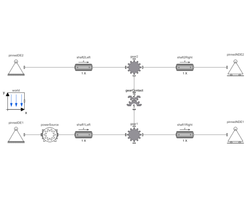
Diagram
Wolfram Language
SystemModel["RotatingMachinery.Examples.Gears.SpurGears.GearTrain"]
Information
Studying a Gear Train
This example teaches how to model a gear train and how to study gear contact dynamics.
Figure 1 shows a gear train consisting of two-wheel gears.
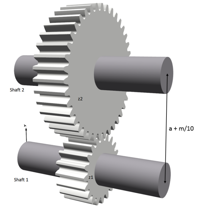
Figure 1: Gear train.
The initial angles of the gearwheels, InitialRotationWheel1 and InitialRotationWheel2, are calculated in the model to have the gear teeth meshed correctly in animations. Flexible beam elements are used for the shaft. The number of elements in the shaft can be changed for a higher/lower detail level. The shaft is mounted on pinned support.
A pinned support only restricts the movement in the translational direction, but there is no restriction to rotation around the axes. To avoid building in axial forces, the pinned support to the right is axially free (pinnedNDE1 and pinnedNDE2), as illustrated by the icons, where the right-hand supports are placed on rollers, as shown in Figure 2.
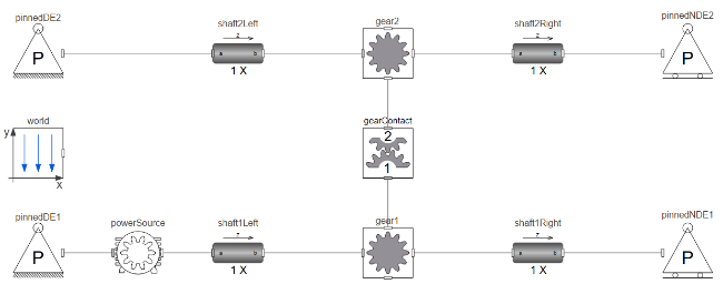
Figure 2: Gear train diagram.
Figure 3 shows the gear parameter tab where gear geometry, number of teeth and gear module are set. For both spur gears (gear1 and gear2), module m should be set the same since they form a gear mesh.
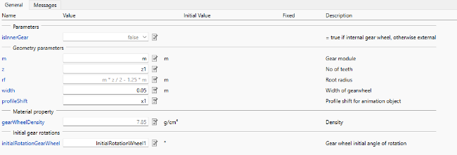
Figure 3: Gear parameter tab.
The distances between the shafts, h, are calculated as follows:
h = a + m/10,
where a = (m * z1 + m * z2) / 2, and m is the gear module, and z1 and z2 are the numbers of the gear teeth.
The clearances are chosen rather large to m/10 for illustration purposes in this example. The position of Shaft 2 is vertically above the Shaft 1.
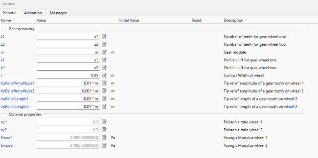
Figure 4: Gear contact parameter tab.
Figure 4 depicts the gear contact parameters tab of the gearForceCalculation component. In this component, contact forces and interaction dynamics are calculated by taking into account the geometry and material properties of the connecting gears.
The indentation depths of the teeth and Hertz contact states are shown in Figure 5. There is no state where two pairs have no contact simultaneously.
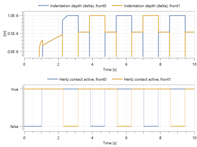
Figure 5: Tooth indentation depths.
In the meantime, the indentation depths increase as the shaft speed increases, reaching the total depth for the corresponding shaft speed and torques.
Parameters (9)
| m |
Value: 0.005 Type: Module (m) Description: Gear module |
|---|---|
| a |
Value: (m * z1 + m * z2) / 2 Type: Distance (m) Description: Distance from wheel center 1 to wheel center 2 |
| alpha0 |
Value: 20 * Modelica.Constants.pi / 180 Type: Angle (rad) Description: Reference profile angle |
| z1 |
Value: 20 Type: Integer Description: Number of teeth in wheel one |
| z2 |
Value: 39 Type: Integer Description: Number of teeth in wheel two |
| x1 |
Value: 0 Type: Real Description: Profile shift for gear wheel one |
| x2 |
Value: -0.1 Type: Real Description: Profile shift for gear wheel two |
| InitialRotationWheel1 |
Value: 90 - 360 / z1 * floor(90 / 360 * z1) Type: Angle_deg (°) Description: Gear wheel initial angle of rotation shaft 1 |
| InitialRotationWheel2 |
Value: 270 - 360 / z2 * (floor(270 / 360 * z2) + 0.5) Type: Angle_deg (°) Description: Gear wheel initial angle of rotation shaft 2 |
Components (13)
| world |
Type: World Description: World coordinate system + gravity field + default animation definition |
|
|---|---|---|
| pinnedDE1 |
Type: PinnedDriveEnd Description: Component that can act as a pinned drive end to a beam, containing different options |
|
| pinnedNDE1 |
Type: PinnedNonDriveEnd Description: Component that can act as a pinned non-drive end to a beam, containing different options |
|
| shaft1Left |
Type: CylindricalBeam Description: Class with a flexible cylindrical beam |
|
| shaft1Right |
Type: CylindricalBeam Description: Class with a flexible cylindrical beam |
|
| pinnedDE2 |
Type: PinnedDriveEnd Description: Component that can act as a pinned drive end to a beam, containing different options |
|
| pinnedNDE2 |
Type: PinnedNonDriveEnd Description: Component that can act as a pinned non-drive end to a beam, containing different options |
|
| shaft2Left |
Type: CylindricalBeam Description: Class with a flexible cylindrical beam |
|
| shaft2Right |
Type: CylindricalBeam Description: Class with a flexible cylindrical beam |
|
| gear1 |
Type: SpurGear Description: Spur gear with mass, rotations and visualization |
|
| gear2 |
Type: SpurGear Description: Spur gear with mass, rotations and visualization |
|
| gearContact |
Type: GearForceCalculation Description: Class calculating gear mesh contact forces |
|
| powerSource |
Type: Motor Description: Class for applying a torque to generate a desired angular velocity |

