WOLFRAM SYSTEM MODELER
PinnedNonDriveEndComponent that can act as a pinned non-drive end to a beam, containing different options |
|
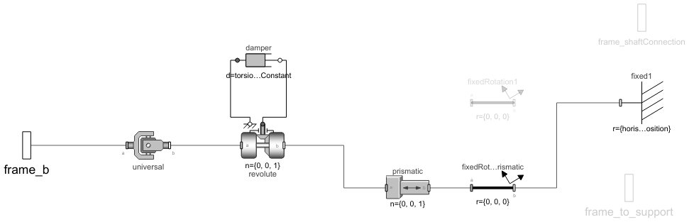
Diagram
Wolfram Language
In[1]:=
SystemModel["RotatingMachinery.Supports.PinnedNonDriveEnd"]
Out[1]:=
Information
Hinge Support - Pinned Non-drive End
This class contains components that act as support to a beam. Depending on the settings of the parameters, the support will act as pinned (hinged) or pinned-free (roller) support. The default setting is a pinned support with a free position in the axial direction (z axis).
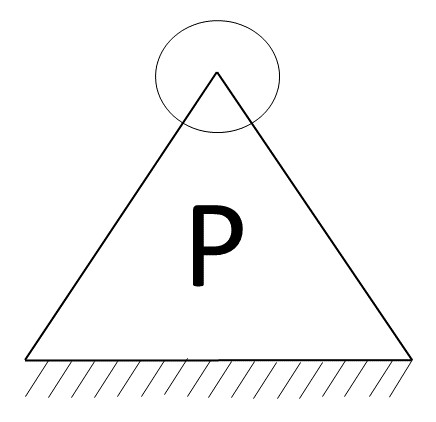
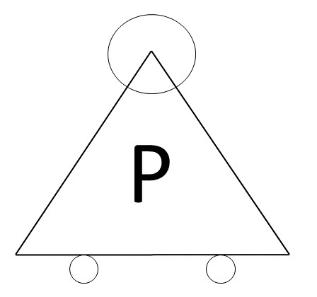
Figure 1: Pinned supports [1].
Preceding are two images showing the difference in setting the axialFixed = true (left) or false (right).
This component acts as the non-drive end because the condition of the initial revolute angle (revolute.phi) is set to fixed = false. In its counter-class, PinnedDriveEnd, the initial revolute angle is set to fixed = true. This means that the drive end will set the initial condition for the components connected to it, while the non-drive end will follow.
Parameters:
useFlangeSupport= Set totrueif the support should be connected to en external flangeaxialFixed= Set totrueif the support should act as only a pinned support; set tofalseif the support should act as a pinned-free support. If set to true, the following parameters will be relevant:AxialPosition= Defines the axial position (z axis) of the fixed point the beam is connected toHorizontalPosition= Defines the horizontal position (x axis) of the fixed point the beam is connected toVerticalPosition= Defines the vertical position (y axis) of the fixed point the beam is connected to
shaftConnection= Set totrueif a rotating shaft flange should be connected to flange b
References
[1] Schmid, S. R., B. J. Hamrock and Bo. O. Jacobson. Fundamentals of Machine Elements. CRC Press, 2013.
Parameters (8)
| useFlangeSupport |
Value: false Type: Boolean Description: = true, if there is a need to connect to an external flange support |
|---|---|
| axialFixed |
Value: false Type: Boolean Description: = true, if a fixed axial position in z direction should be set. To avoid built-in axial stresses, driving end should normally be fixed |
| shaftConnection |
Value: false Type: Boolean Description: = true, if a rotating shaft flange will be used. I.e. a connection to flange b |
| angle |
Value: 0 Type: Angle_deg (°) Description: Initial torsional rotation |
| torsionalDampingConstant |
Value: 0 Type: RotationalDampingConstant (N⋅m⋅s/rad) Description: Damping constant |
| axialPosition |
Value: 0 Type: Length (m) Description: Axial position in z direction |
| horisontalPosition |
Value: 0 Type: Length (m) Description: Horisontal position in x direction |
| verticalPosition |
Value: 0 Type: Length (m) Description: Vertical position in y direction |
Connectors (3)
| frame_b |
Type: Frame_b Description: Coordinate system fixed to the component with one cut-force and cut-torque (non-filled rectangular icon) |
|
|---|---|---|
| frame_to_support |
Type: Frame_b Description: Coordinate system fixed to the component with one cut-force and cut-torque (non-filled rectangular icon) |
|
| frame_shaftConnection |
Type: Frame_b Description: Coordinate system fixed to the component with one cut-force and cut-torque (non-filled rectangular icon) |
Components (7)
| revolute |
Type: Revolute Description: Revolute joint (1 rotational degree-of-freedom, 2 potential states, optional axis flange) |
|
|---|---|---|
| universal |
Type: Universal Description: Universal joint (2 degrees-of-freedom, 4 potential states) |
|
| fixed1 |
Type: Fixed Description: Frame fixed in the world frame at a given position |
|
| prismatic |
Type: Prismatic Description: Prismatic joint (1 translational degree-of-freedom, 2 potential states, optional axis flange) |
|
| fixedRotationPrismatic |
Type: FixedRotation Description: Fixed translation followed by a fixed rotation of frame_b with respect to frame_a |
|
| damper |
Type: Damper Description: Linear 1D rotational damper |
|
| fixedRotation1 |
Type: FixedRotation Description: Fixed translation followed by a fixed rotation of frame_b with respect to frame_a |
Used in Examples (9)
|
RotatingMachinery.Examples.BearingAnalysis Two roller bearings on flexible supports |
|
|
RotatingMachinery.Examples.BearingAnalysis Frequency analysis of a bearing defect on a simple shaft mounted on a structure |
|
|
RotatingMachinery.Examples.Gears.SpurGears Building a two-wheeled gear train on shafts |
|
|
RotatingMachinery.Examples.Gears.SpurGears Construction of triple gearbox on three shafts |
|
|
RotatingMachinery.Examples.JeffcottRotorDamping Determine shaft damping |
|
|
RotatingMachinery.Examples.JeffcottRotorDamping A basic Jeffcott rotor with internal and external damping |
|
|
RotatingMachinery.Examples.RotorBalancing An unbalanced rotor stabilized by balancing planes |
|
|
RotatingMachinery.Examples.Shafts Inspection of an axle's vibrations |
|
|
RotatingMachinery.Examples.Shafts Inspection of a car axle deflection on tires |
Used in Components (1)
|
RotatingMachinery.Gears.PlanetaryGears This component is a three-shaft gearbox and is a part of the wind turbine gearbox |