WOLFRAM SYSTEM MODELER
GearboxThis component is a three-shaft gearbox and is a part of the wind turbine gearbox |
|
Diagram
Wolfram Language
In[1]:=
SystemModel["RotatingMachinery.Gears.PlanetaryGears.Gearbox"]
Out[1]:=
Information
Gearbox
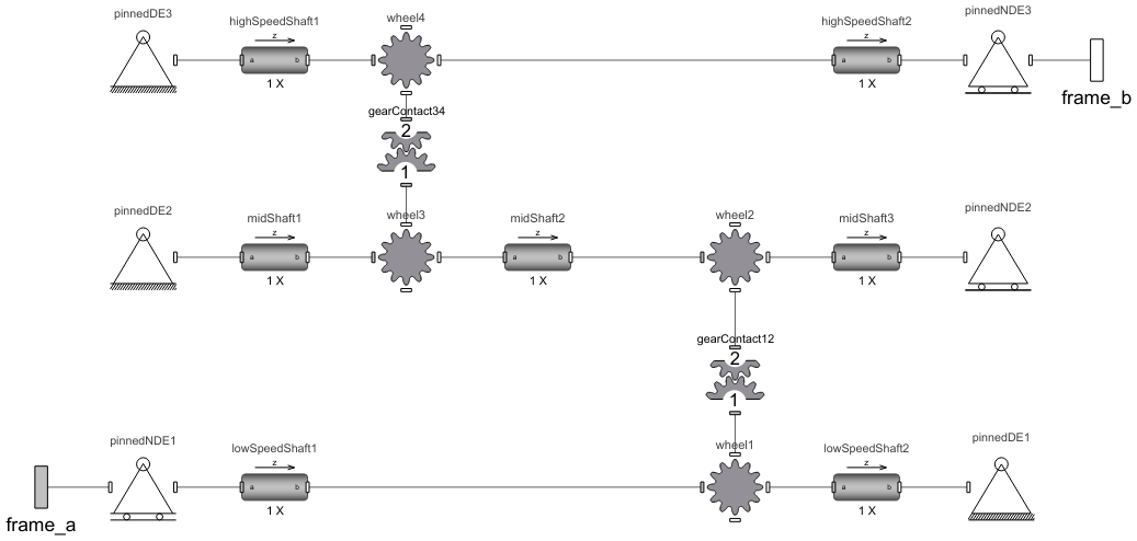
This component is a three-shaft gearbox, [1, 2, 4], and is a part of the wind turbine gearbox [1, 3].
The GearTrain example shows how a gear with two wheels can be built up. The distances between the shafts are calculated from the number of teeth (z1 and z2, respectively), the module and clearances. The clearances are chosen rather large, m/10, for illustration purposes. The position of shaft2 is vertical above shaft1.
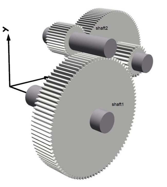
Figure 1: Three-shaft gearbox.
The frame_a should be connected to the low-speed shaft, whereas the flame_b should be to the high-speed shaft.
Figure 2 shows the parameters tab for the gearbox component. Geometry of the gears is specified by setting the corresponding parameters: number of teeth, modules, reference profile angles.
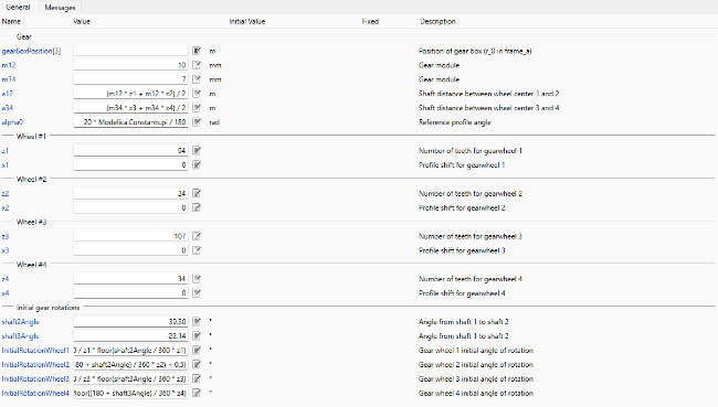
Figure 2: Three-shaft gearbox parameters tab.
The initial angles of the gearwheels are also calculated in the parameters tab so that the gears' teeth are in contact. For applications such as this one, it is normally necessary to start without initial forces.
References
[1] Dahl, M., H. Wettergren, and H. Tidefelt. "Modelica Spur Gears with Hertzian Contact Forces." Proceedings of the 12th International Modelica Conference, Prague, Czech Republic, May 15-17, 2017. Linköping Electronic Conference Proceedings 132, no. 82 (2017): 755-763. http://dx.doi.org/10.3384/ecp17132755.
[2] Van der Lunden, F. L. J. and P. H. Vazques de Souza Silva. "Modelling and Simulating the Efficiency and Elasticity of Gearboxes." Proceedings of the 7th International Modelica Conference, Como; Italy, Sep 20-22, 2009. Linköping Electronic Conference Proceedings 43, no. 29 (2009): 270-277. http://dx.doi.org/10.3384/ecp09430052.
[3] Kosenko, I. and I. Gusev. "Implementation of the Spur Involute Gear Model on Modelica." Proceedings of the 8th International Modelica Conference, Dresden; Germany, Mar 20-22, 2011. Linköping Electronic Conference Proceedings 63, no. 35 (2011): 315-328. http://dx.doi.org/10.3384/ecp11063315.
[4] B. Paul. Kinematics and Dynamics of Planar Machinery. Prentice Hall, 1979.
Parameters (21)
| gearBoxPosition |
Type: Position[3] (m) Description: Position of gear box (r_0 in frame_a) |
|---|---|
| m12 |
Value: 0.010 Type: Module (m) Description: Gear module |
| m34 |
Value: 0.007 Type: Module (m) Description: Gear module |
| a12 |
Value: (m12 * z1 + m12 * z2) / 2 Type: Distance (m) Description: Shaft distance between wheel center 1 and 2 |
| a34 |
Value: (m34 * z3 + m34 * z4) / 2 Type: Distance (m) Description: Shaft distance between wheel center 3 and 4 |
| alpha0 |
Value: 20 * Modelica.Constants.pi / 180 Type: Angle (rad) Description: Reference profile angle |
| z1 |
Value: 94 Type: Integer Description: Number of teeth for gearwheel 1 |
| x1 |
Value: 0 Type: Real Description: Profile shift for gearwheel 1 |
| z2 |
Value: 24 Type: Integer Description: Number of teeth for gearwheel 2 |
| x2 |
Value: 0 Type: Real Description: Profile shift for gearwheel 2 |
| z3 |
Value: 107 Type: Integer Description: Number of teeth for gearwheel 3 |
| x3 |
Value: 0 Type: Real Description: Profile shift for gearwheel 3 |
| z4 |
Value: 34 Type: Integer Description: Number of teeth for gearwheel 4 |
| x4 |
Value: 0 Type: Real Description: Profile shift for gearwheel 4 |
| fullTurn |
Value: 360 Type: Angle_deg (°) Description: Angle in degree |
| shaft2Angle |
Value: 39.30 Type: Angle_deg (°) Description: Angle from shaft 1 to shaft 2 |
| shaft3Angle |
Value: -22.14 Type: Angle_deg (°) Description: Angle from shaft 1 to shaft 2 |
| InitialRotationWheel1 |
Value: shaft2Angle - fullTurn / z1 * floor(shaft2Angle / fullTurn * z1) Type: Angle_deg (°) Description: Gear wheel 1 initial angle of rotation |
| InitialRotationWheel2 |
Value: 180 + shaft2Angle - fullTurn / z2 * (floor((180 + shaft2Angle) / fullTurn * z2) + 0.5) Type: Angle_deg (°) Description: Gear wheel 2 initial angle of rotation |
| InitialRotationWheel3 |
Value: shaft3Angle - fullTurn / z3 * floor(shaft3Angle / fullTurn * z3) Type: Angle_deg (°) Description: Gear wheel 3 initial angle of rotation |
| InitialRotationWheel4 |
Value: 180 + shaft3Angle - fullTurn / z4 * floor((180 + shaft3Angle) / fullTurn * z4) Type: Angle_deg (°) Description: Gear wheel 4 initial angle of rotation |
Connectors (2)
Components (19)
| midShaft1 |
Type: CylindricalBeam Description: Class with a flexible cylindrical beam |
|
|---|---|---|
| midShaft3 |
Type: CylindricalBeam Description: Class with a flexible cylindrical beam |
|
| lowSpeedShaft1 |
Type: CylindricalBeam Description: Class with a flexible cylindrical beam |
|
| lowSpeedShaft2 |
Type: CylindricalBeam Description: Class with a flexible cylindrical beam |
|
| midShaft2 |
Type: CylindricalBeam Description: Class with a flexible cylindrical beam |
|
| highSpeedShaft1 |
Type: CylindricalBeam Description: Class with a flexible cylindrical beam |
|
| highSpeedShaft2 |
Type: CylindricalBeam Description: Class with a flexible cylindrical beam |
|
| pinnedDE1 |
Type: PinnedNonDriveEnd Description: Component that can act as a pinned non-drive end to a beam, containing different options |
|
| pinnedDE2 |
Type: PinnedDriveEnd Description: Component that can act as a pinned drive end to a beam, containing different options |
|
| pinnedNDE2 |
Type: PinnedNonDriveEnd Description: Component that can act as a pinned non-drive end to a beam, containing different options |
|
| wheel1 |
Type: SpurGear Description: Spur gear with mass, rotations and visualization |
|
| wheel2 |
Type: SpurGear Description: Spur gear with mass, rotations and visualization |
|
| wheel3 |
Type: SpurGear Description: Spur gear with mass, rotations and visualization |
|
| pinnedDE3 |
Type: PinnedDriveEnd Description: Component that can act as a pinned drive end to a beam, containing different options |
|
| pinnedNDE3 |
Type: PinnedNonDriveEnd Description: Component that can act as a pinned non-drive end to a beam, containing different options |
|
| wheel4 |
Type: SpurGear Description: Spur gear with mass, rotations and visualization |
|
| gearContact12 |
Type: GearForceCalculation Description: Class calculating gear mesh contact forces |
|
| gearContact34 |
Type: GearForceCalculation Description: Class calculating gear mesh contact forces |
|
| pinnedNDE1 |
Type: PinnedDriveEnd Description: Component that can act as a pinned drive end to a beam, containing different options |
Used in Examples (2)
|
RotatingMachinery.Examples.Gears.PlanetaryGears Building a three-shaft gearbox; WindTurbine Part II |
|
|
RotatingMachinery.Examples.Gears.PlanetaryGears Assembly of a planetary gear and a three-shafted gearbox; Part I and Part II |