WOLFRAM SYSTEM MODELER
ThreeShaftGearboxBuilding a three-shaft gearbox; WindTurbine Part II |
|
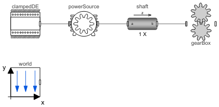
Diagram
Wolfram Language
In[1]:=
SystemModel["RotatingMachinery.Examples.Gears.PlanetaryGears.ThreeShaftGearbox"]
Out[1]:=
Information
Wind Turbine Part II: Build a Three-Shaft Gearbox for Higher Transmission Ratios
This example demonstrates a three-shaft gearbox.
It has a high transmission ratio to multiply the slow input shaft speed with high torques. It is the second part of the wind turbine assembly.
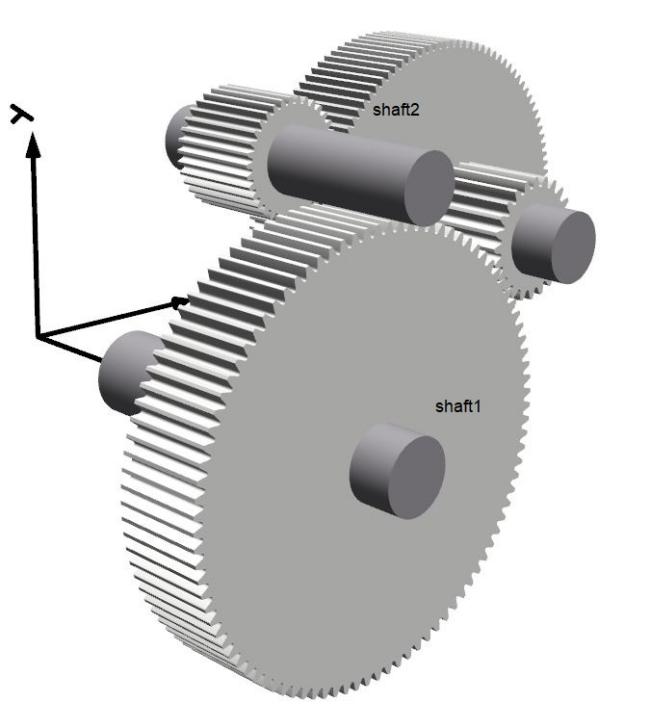
Figure 1: Three-shaft gearbox.
The initial positions and initial angles are calculated automatically to give a smooth start of the simulation. Power is applied to the slowest shaft, which means that the output shaft will have a much higher rotational speed. 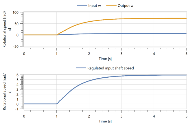
Figure 2: Rotational speeds of input and output shafts.
Figure 2 shows the input and output shaft speeds. As seen, to get smoother performances while running the system, the input shaft is regulated by a PID controller.
Components (5)
| shaft |
Type: CylindricalBeam Description: Class with a flexible cylindrical beam |
|
|---|---|---|
| world |
Type: World Description: World coordinate system + gravity field + default animation definition |
|
| gearBox |
Type: Gearbox Description: This component is a three-shaft gearbox and is a part of the wind turbine gearbox |
|
| clampedDE |
Type: ClampedDriveEnd Description: Component that can act as a clamped drive end to a beam, containing different options |
|
| powerSource |
Type: Motor Description: Class for applying a torque to generate a desired angular velocity |