WOLFRAM SYSTEM MODELER
MotorClass for applying a torque to generate a desired angular velocity |
|
Diagram
Wolfram Language
SystemModel["RotatingMachinery.Sources.Motor"]

Information
Motor
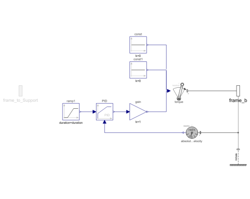
A component generates a torque set by a PID controller that tries to keep a desired angular velocity.
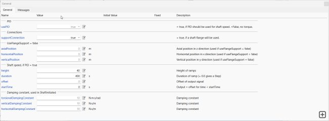
The input to the PID (the desired angular velocity) follows a ramp signal. The desired ramp signal can be set under Shaft speed in the General tab.

There are two options for connecting frame_b to components. If the parameter supportConnection is set to false, frame_b will connect to a component called ShaftInitiated, which is a universal joint, a revolute joint and then two prismatic joints connected to a fixed point. This option will ground frame_b at the fixed end but still have flexibility in all but the axial direction (z axis). The fixed end is needed for initialization and to ground the revolute to apply torque.
When usePID is false, the motor transmits torque from the connected shaft, making it ideal for shaft-initiated torque application due to its flexibility and ease of equation solving.
If the other option is chosen, with the supportConnection set to true, frame_b will be connected to frame_to_Support, which can be connected to anything. This means that PowerSource will only generate a torque on frame_b.
There are many examples where this component is used under the Examples package.
Parameters (12)
| usePID |
Value: true Type: Boolean Description: = true, if PID should be used for shaft speed. =False, no torque. |
|---|---|
| supportConnection |
Value: false Type: Boolean Description: = true, if a shaft flange will be used. |
| axialPosition |
Value: 0 Type: Length (m) Description: Axial position in z direction (used if useFlangeSupport = false) |
| horisontalPosition |
Value: 0 Type: Length (m) Description: Horisontal position in x direction (used if useFlangeSupport = false) |
| verticalPosition |
Value: 0 Type: Length (m) Description: Vertical position in y direction (used if useFlangeSupport = false) |
| height |
Value: 1 Type: Real Description: Height of ramps |
| duration |
Value: 1 Type: Time (s) Description: Duration of ramp (= 0.0 gives a Step) |
| offset |
Value: 0 Type: Real Description: Offset of output signal |
| startTime |
Value: 1 Type: Time (s) Description: Output = offset for time < startTime |
| torsionalDampingConstant |
Value: 10 Type: RotationalDampingConstant (N⋅m⋅s/rad) Description: Damping constant |
| verticalDampingConstant |
Value: 10 Type: TranslationalDampingConstant (N⋅s/m) Description: Damping constant |
| horisontalDampingConstant |
Value: 10 Type: TranslationalDampingConstant (N⋅s/m) Description: Damping constant |
Connectors (2)
Components (8)
| torque |
Type: WorldTorque Description: External torque acting at frame_b, defined by 3 input signals and resolved in frame world, frame_b or frame_resolve |
|
|---|---|---|
| const |
Type: Constant Description: Generate constant signal of type Real |
|
| const1 |
Type: Constant Description: Generate constant signal of type Real |
|
| absoluteAngularVelocity |
Type: AbsoluteAngularVelocity Description: Measure absolute angular velocity of frame connector |
|
| gain |
Type: Gain Description: Output the product of a gain value with the input signal |
|
| PID |
Type: LimPID Description: P, PI, PD, and PID controller with limited output, anti-windup compensation, setpoint weighting and optional feed-forward |
|
| ramp1 |
Type: Ramp Description: Generate ramp signal |
|
| shaftInitiated |
Type: ShaftInitiated Description: The main purpose for this component is to initiate a shaft supported with rolling bearings |
Used in Examples (20)
|
RotatingMachinery.Examples.BearingAnalysis Study of individual roller forces |
|
|
RotatingMachinery.Examples.BearingAnalysis Comparison of a defect and regular bearing |
|
|
RotatingMachinery.Examples.BearingAnalysis Two roller bearings' responses under a loaded shaft |
|
|
RotatingMachinery.Examples.BearingAnalysis Two roller bearings on flexible supports |
|
|
RotatingMachinery.Examples.BearingAnalysis Frequency analysis of a bearing defect on a simple shaft mounted on a structure |
|
|
RotatingMachinery.Examples.BearingAnalysis Comparison bearings from a selection list |
|
|
RotatingMachinery.Examples.BearingAnalysis Study of individual roller forces |
|
|
RotatingMachinery.Examples.StabilityAnalysis Finding whirling frequencies of a rotating shaft: Part I |
|
|
RotatingMachinery.Examples.StabilityAnalysis Finding whirling frequencies of a rotating shaft: Part II |
|
|
RotatingMachinery.Examples.Gears.SpurGears Building a two-wheeled gear train on shafts |
|
|
RotatingMachinery.Examples.Gears.SpurGears Construction of triple gearbox on three shafts |
|
|
RotatingMachinery.Examples.Gears.PlanetaryGears A basic planetary gear application; WindTurbine Part I |
|
|
RotatingMachinery.Examples.Gears.PlanetaryGears Building a three-shaft gearbox; WindTurbine Part II |
|
|
RotatingMachinery.Examples.Gears.PlanetaryGears Assembly of a planetary gear and a three-shafted gearbox; Part I and Part II |
|
|
RotatingMachinery.Examples.JeffcottRotorDamping A basic Jeffcott rotor with internal and external damping |
|
|
RotatingMachinery.Examples.RotorBalancing An unbalanced rotor stabilized by balancing planes |
|
|
RotatingMachinery.Examples.ContactAnalysis Study of a running up clamped free rotor |
|
|
RotatingMachinery.Examples.ContactAnalysis Inspection of deflection of a free rotor without clearance |
|
|
RotatingMachinery.Examples.ContactAnalysis Calculation of deflection for a rotor with a surrounding and a clearance |
|
|
RotatingMachinery.Examples.ContactAnalysis Application of a running down rotor deflection with a clearance |

