WOLFRAM SYSTEM MODELER
BearingRollerForcesSimplifiedStudy of individual roller forces |
|
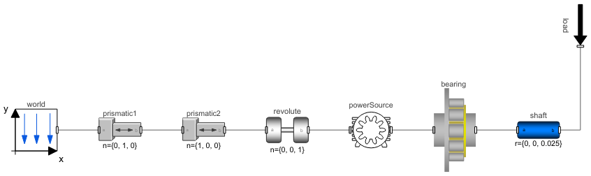
Diagram
Wolfram Language
In[1]:=
SystemModel["RotatingMachinery.Examples.BearingAnalysis.BearingRollerForcesSimplified"]
Out[1]:=
Information
Study of Individual Bearing Roller Forces
This example teaches how to model a bearing and how roller forces are illustrated in animations.
The model contains a motor applying torque to a cylindrical bearing. There is also a load applied through a shaft. The cylindrical bearing is of the type NSK NU 207 EW. Bearing dimensions for this specific bearing are used in the model and can be found by clicking the bearing and then looking in the Bearing Dimensions tab.
Figure 1 illustrates the forces on a roller assembly using arrows. Except for the first roller (blue arrow), all internal roller forces are depicted by green arrows (rollerAssembly.rollerPart.Q). The blue arrow shows the total force on the first roller, including the defect force. Since there is no defect in the model, green roller forces are equal to the blue roller force (total force = internal roller force + defect force).
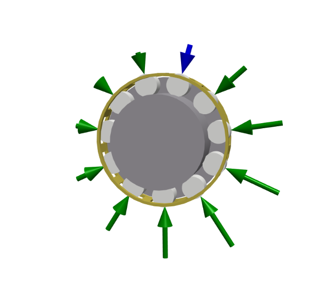 Figure 1: Animated roller forces (-90°).
Figure 2 shows how the total roller force (rollerAssembly.rollerPart.frame_b[1]) varies under the applied load.
 Figure 2: Roller forces.
Figure 3 shows the variation in roller forces (represented by the blue arrow and one green arrow opposite to it) with the angular position as a load is applied. As the bearing rotates, the pressure on the rollers changes, with the bottom rollers experiencing the highest forces. It is also seen that the forces increase as the rollers approach the bottom.
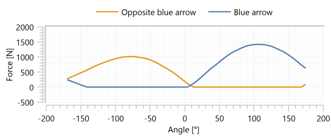 Figure 3: Roller forces vs. angles.
The top roller does not have force if there is no preloading, but in this bearing, preloaded rollers are used to eliminate internal play. However, since the applied load gets large enough, the roller at the top reaches zero.
For more details on bearing analysis, see this blog post.
Parameters (1)
| appliedLoad |
Value: -4000 Type: Force (N) Description: The load applied to the shaft |
|---|
Components (8)
| world |
Type: World Description: World coordinate system + gravity field + default animation definition |
|
|---|---|---|
| bearing |
Type: NSK_NU_207_EW Description: Roller bearing parameterized with values corresponding to NSK NU 207 EW |
|
| powerSource |
Type: Motor Description: Class for applying a torque to generate a desired angular velocity |
|
| revolute |
Type: Revolute Description: Revolute joint (1 rotational degree-of-freedom, 2 potential states, optional axis flange) |
|
| prismatic2 |
Type: Prismatic Description: Prismatic joint (1 translational degree-of-freedom, 2 potential states, optional axis flange) |
|
| prismatic1 |
Type: Prismatic Description: Prismatic joint (1 translational degree-of-freedom, 2 potential states, optional axis flange) |
|
| shaft |
Type: BodyCylinder Description: Rigid body with cylinder shape. Mass and animation properties are computed from cylinder data and density (12 potential states) |
|
| load |
Type: Force Description: Class that can apply forces along x, y and z axes with a defined interval and amplitude |