WOLFRAM SYSTEM MODELER
TripleGearTransmissionConstruction of triple gearbox on three shafts |
|
Diagram
Wolfram Language
SystemModel["RotatingMachinery.Examples.Gears.SpurGears.TripleGearTransmission"]

Information
Building a Triple-Gear Transmission
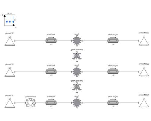
This three-shaft example shows contact forces on gear teeth of a more complex gearbox.
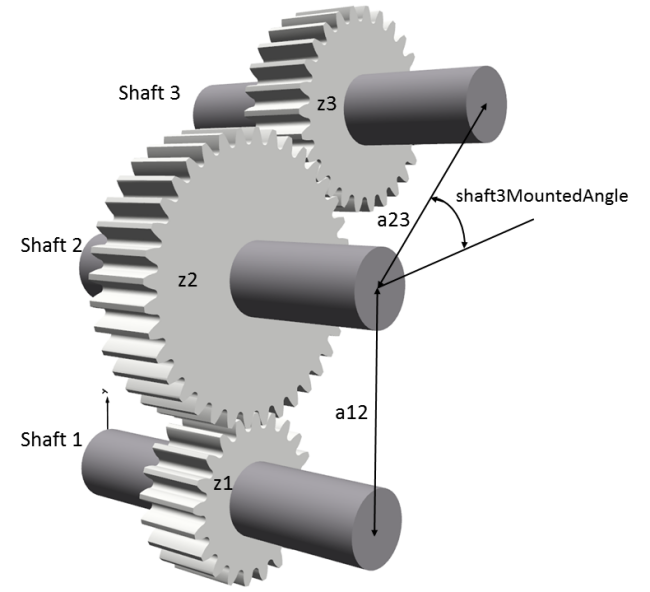
In this example, the distances between the shafts are calculated from the number of teeth (z1, z2 and z3, respectively), the module and clearances.

Figure 1: Triple gear mesh.
The clearances are chosen rather large to m/10 for illustration purposes. The position of Shaft 2 is vertically above Shaft 1, but the position of Shaft 3 can be chosen arbitrarily with the shaft3MountedAngle. The initial angles of the gearwheels are also calculated in the example to start the teeth in contact.

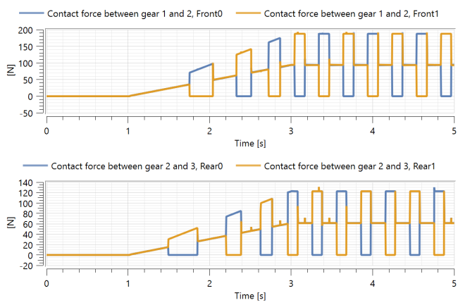
Figure 2: Teeth contact forces.
The contact forces between all gears are shown in Figure 2. These forces are the reason for the indentations that are plastic deformation to the tooth surfaces covering small areas. The high-contact stress results in the hard particle plastically deforming the tooth and indenting the gear.
Parameters (14)
| m |
Value: 0.005 Type: Length (m) Description: Gear module |
|---|---|
| a12 |
Value: (m * z1 + m * z2) / 2 + m / 10 Type: Distance (m) Description: Distance from wheel center 1 to wheel center 2 |
| a23 |
Value: (m * z2 + m * z3) / 2 + m / 10 Type: Distance (m) Description: Distance from wheel center 2 to wheel center 3 |
| alpha0 |
Value: 20 * Modelica.Constants.pi / 180 Type: Angle (rad) Description: Reference profile angle |
| z1 |
Value: 21 Type: Integer Description: Number of teeth in wheel one |
| z2 |
Value: 37 Type: Integer Description: Number of teeth in wheel two |
| z3 |
Value: 27 Type: Integer Description: Number of teeth in wheel three |
| x1 |
Value: 0 Type: Real Description: Profile shift for gear wheel one |
| x2 |
Value: 1e-01 Type: Real Description: Profile shift for gear wheel two |
| x3 |
Value: 0 Type: Real Description: Profile shift for gear wheel three |
| shaft3MountedAngle |
Value: 45 Type: Angle_deg (°) Description: Shaft mounted angle. 0= Horisontal, 90 = vertical, i.e. above shaft 2 |
| InitialRotationWheel1 |
Value: 90 - 360 / z1 * floor(90 / 360 * z1) Type: Angle_deg (°) Description: Gear wheel initial angle of rotation shaft 1 |
| InitialRotationWheel2 |
Value: 270 - 360 / z2 * (floor(270 / 360 * z2) + 0.5) Type: Angle_deg (°) Description: Gear wheel initial angle of rotation shaft 2 |
| InitialRotationWheel3 |
Value: 180 + shaft3MountedAngle - 360 / z3 * floor((shaft3MountedAngle + 180) / 360 * z3) + z2 / z3 * (shaft3MountedAngle - (360 / z2 * floor(shaft3MountedAngle / 360 * z2) - InitialRotationWheel2 + 360 / z2)) Type: Angle_deg (°) Description: Gear wheel initial angle of rotation shaft 3 |
Components (19)
| world |
Type: World Description: World coordinate system + gravity field + default animation definition |
|
|---|---|---|
| pinnedDE1 |
Type: PinnedDriveEnd Description: Component that can act as a pinned drive end to a beam, containing different options |
|
| pinnedNDE1 |
Type: PinnedNonDriveEnd Description: Component that can act as a pinned non-drive end to a beam, containing different options |
|
| pinnedDE2 |
Type: PinnedDriveEnd Description: Component that can act as a pinned drive end to a beam, containing different options |
|
| pinnedNDE2 |
Type: PinnedNonDriveEnd Description: Component that can act as a pinned non-drive end to a beam, containing different options |
|
| pinnedDE3 |
Type: PinnedDriveEnd Description: Component that can act as a pinned drive end to a beam, containing different options |
|
| pinnedNDE3 |
Type: PinnedNonDriveEnd Description: Component that can act as a pinned non-drive end to a beam, containing different options |
|
| shaft1Left |
Type: CylindricalBeam Description: Class with a flexible cylindrical beam |
|
| shaft1Right |
Type: CylindricalBeam Description: Class with a flexible cylindrical beam |
|
| shaft2Left |
Type: CylindricalBeam Description: Class with a flexible cylindrical beam |
|
| shaft2Right |
Type: CylindricalBeam Description: Class with a flexible cylindrical beam |
|
| gear1 |
Type: SpurGear Description: Spur gear with mass, rotations and visualization |
|
| gear2 |
Type: SpurGear Description: Spur gear with mass, rotations and visualization |
|
| gear3 |
Type: SpurGear Description: Spur gear with mass, rotations and visualization |
|
| shaft3Left |
Type: CylindricalBeam Description: Class with a flexible cylindrical beam |
|
| shaft3Right |
Type: CylindricalBeam Description: Class with a flexible cylindrical beam |
|
| gearContact12 |
Type: GearForceCalculation Description: Class calculating gear mesh contact forces |
|
| gearContact23 |
Type: GearForceCalculation Description: Class calculating gear mesh contact forces |
|
| powerSource |
Type: Motor Description: Class for applying a torque to generate a desired angular velocity |

