WOLFRAM SYSTEM MODELER
GearForceCalculationClass calculating gear mesh contact forces |
|
Diagram
Wolfram Language
In[1]:=
SystemModel["RotatingMachinery.Gears.Components.GearForceCalculation"]
Out[1]:=
Information
Gear Forces
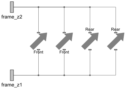
This component contains four different ContactForcePoints components. That means that four spur gear forces are being calculated for four tooth pairs (maximum of two pairs can be in contact at a time) between the gear connected to frame_z1 and the gear connected to frame_z2. The parameters that need to be specified in this component are the material and gear geometry.
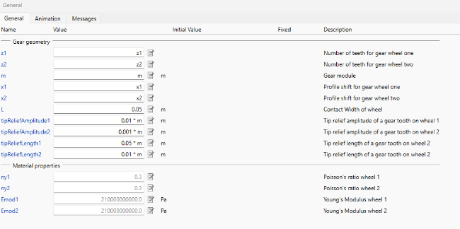
Figure 1: Gear contact parameter tab.
Tip relief, or tip modification, is necessary to avoid transients that occur when teeth come into contact. When two teeth come into contact, there is a deflection due to elastic deformation in the contact zone, which causes one tooth to take all the forces and increases the contact stress on that tooth.
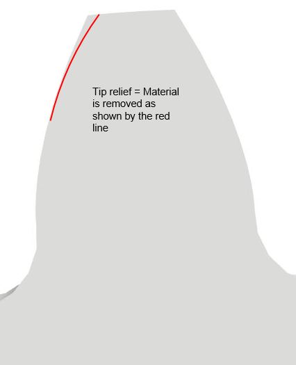
Figure 2: Tip relief.
Figure 2 shows a tip relief implementation. Tip relief related parameters are set by two parameters for each gear, tipReliefAmplitude and tipReliefLength.
The default settings of the ContactForcePoints for a smooth start are as follows:
| ContactForcePoint | isFront | toothIndexShift |
| Front0 | true | 0 |
| Front1 | true | 1 |
| Rear0 | false | 0 |
| Rear1 | false | 1 |
Parameters (12)
| z1 |
Type: Integer Description: Number of teeth for gear wheel one |
|---|---|
| z2 |
Type: Integer Description: Number of teeth for gear wheel two |
| m |
Type: Length (m) Description: Gear module |
| x1 |
Type: Real Description: Profile shift for gear wheel one |
| x2 |
Type: Real Description: Profile shift for gear wheel two |
| N_to_m |
Value: 200000 Type: Real (N/m) Description: Scale factor for animation of forces |
| useDebugPoints |
Value: false Type: Boolean |
| L |
Type: Length (m) Description: Contact Width of wheel |
| tipReliefAmplitude1 |
Value: 0.001 * m Type: Distance (m) Description: Tip relief amplitude of a gear tooth on wheel 1 |
| tipReliefAmplitude2 |
Value: 0.001 * m Type: Distance (m) Description: Tip relief amplitude of a gear tooth on wheel 2 |
| tipReliefLength1 |
Value: 0.01 * m Type: Distance (m) Description: Tip relief length of a gear tooth on wheel 2 |
| tipReliefLength2 |
Value: 0.01 * m Type: Distance (m) Description: Tip relief length of a gear tooth on wheel 2 |
Connectors (2)
Components (4)
| ContactForcePoints_Front0 |
Type: ContactForcePoints Description: Class for calculation of cylindrical contact force between two teeth on a spur gear |
|
|---|---|---|
| ContactForcePoints_Front1 |
Type: ContactForcePoints Description: Class for calculation of cylindrical contact force between two teeth on a spur gear |
|
| ContactForcePoints_Rear0 |
Type: ContactForcePoints Description: Class for calculation of cylindrical contact force between two teeth on a spur gear |
|
| ContactForcePoints_Rear1 |
Type: ContactForcePoints Description: Class for calculation of cylindrical contact force between two teeth on a spur gear |
Used in Examples (3)
|
RotatingMachinery.Examples.Gears.SpurGears Building a two-wheeled gear train on shafts |
|
|
RotatingMachinery.Examples.Gears.SpurGears Analyzing the clearance between gears |
|
|
RotatingMachinery.Examples.Gears.SpurGears Construction of triple gearbox on three shafts |
Used in Components (2)
|
RotatingMachinery.Gears.PlanetaryGears This component is a three-shaft gearbox and is a part of the wind turbine gearbox |
|
|
RotatingMachinery.Gears.PlanetaryGears Class containing a basic planetary gear model |