WOLFRAM SYSTEM MODELER
ContactForcePointsClass for calculation of cylindrical contact force between two teeth on a spur gear |
|
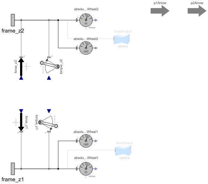
Diagram
Wolfram Language
In[1]:=
SystemModel["RotatingMachinery.Gears.Components.ContactForcePoints"]
Out[1]:=
Information
Contact Force Calculations
This model calculates the force between two teeth on a spur gear. It also determines when this force should be applied, dependent on the isFront parameter and toothIndexShift.
Another parameter that can be set on each ContactForcePointsInner is useDebugPoints. This will enable an animation object to be visible at the base of the tooth of that component. This can be used to keep track of which component is trying to calculate which force, and if that force seems to be in the appropriate place. More information can be found in ContactForcePoints.
At initialization, a tooth pair will be selected with different indices, one tooth on the gear in frame_z1 and one tooth on the gear in frame_z2. Normally, four of these components are put in the component GearForceCalculation, which results in four tooth pairs. To visualize where these tooth pairs are located, it is possible to turn on a parameter called "debugPoints", which will result in the following visualization.
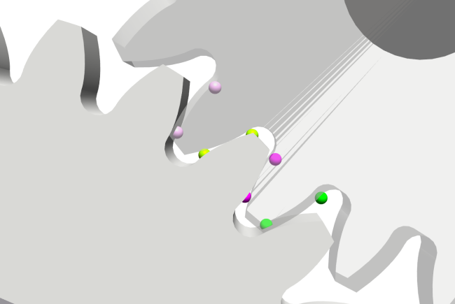
Figure 1: Debug points.
Two spheres with the same color should be paired up together. This way, you can see if the forces have been placed at appropriate positions.
Contact Ratio
The contact ratio is calculated continuously and can be found by plotting the variable epsilon. It is calculated through the following equations:
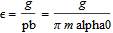

where index 1 refers to wheel 1 and index 2 to wheel 2.
The contact ratio should never be below 1 for a stable simulation result. If it is below 1, it might mean that the gears are too far apart, and the conditions for ContactForcePoints to switch teeth might not be triggered correctly.
Forces
The forces calculated depend on the distance between two coordinates in a tooth pair. The coordinates will always be on the line of contact (LoC). The force used is based on Hertz contact theory between two cylinders.
It is assumed that the teeth have contact in the whole gearwheel width, i.e. no crowning. Equation for the Hertz contact width b:
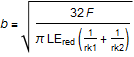
and displacement of cylinders, delta:
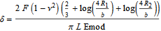
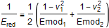
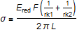
where F is the force, nu is the Poisson ratio, Emod is Young's modulus, L is the length of the cylinder, and R is the radius of the cylinder. To simplify the equations, Ered is defined as:
With the preceding equations, delta as a function of contact force can be solved. However, the simulation time can be improved if the equations are rewritten as follows. The error in deformation delta is normally less than 1% and in contact stress even better.
The relation between contact force and indentation depth can be written as:

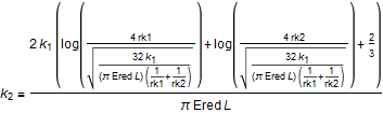
where with good accuracy, k1 can be set to:
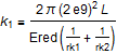
and
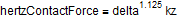
Then, the load indentation depth can be written as:

With the notation used in the source code:
This describes the force dependent on indentation depth and geometry of the cylinders. The geometry of the cylinders in contact will change when moving on the line of contact, i.e. the curvature radii rk1 and rk2 will either start with a small radius and increase when moving on the LoC, or start with a big radius and decrease when moving on the LoC. They are defined through the following equation:
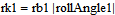
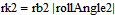
where rb1 and rb2 are the base circle radii of wheel 1 and wheel 2, respectively, and ToothBaseAngle describes the angle from the start of when the base of a tooth intersects with the LoC to its current angle. LoCTangent is a vector describing the LoC tangent line.
The forces are visualized by a blue and red arrow for each tooth pair, representing the force from wheel one and wheel two, respectively.
Contact Stress
The Hertz contact stress for a cylinder contact is:
ISO Standard Calculation
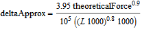
To be able to compare the forces from simulation to theoretical textbook values, there is a secondary implementation of the force. What can be compared is the contact pressure sigmaH and the indentation depth delta. The theoretical versions of these variables are called sigmaHTheoretical and deltaApprox. The theoretical values are calculated according to the formulas below:
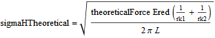
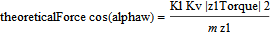
where Kl is the load factor and Kv is the dynamic load factor (default value for both is 1).

where zH is the form factor, zM is the material factor, and zE is the gear ratio factor.
References
[1] Dahl, M., H. Wettergren, and H. Tidefelt. "Modelica Spur Gears with Hertzian Contact Forces." Proceedings of the 12th International Modelica Conference, Prague, Czech Republic, May 15-17, 2017. Linköping Electronic Conference Proceedings 132, no. 82 (2017): 755-763. http://dx.doi.org/10.3384/ecp17132755.
Parameters (38)
| L |
Type: Length (m) Description: Contact Width of wheel |
|---|---|
| N_to_m |
Type: Real (N/m) Description: Scale factor for animation of forces |
| m |
Value: 0.005 Type: Module (m) Description: Gear module |
| alpha0 |
Value: 20 * Modelica.Constants.pi / 180 Type: Angle (rad) Description: Reference profile angle |
| z1 |
Type: Integer Description: Number of teeth in wheel one |
| z2 |
Type: Integer Description: Number of teeth in wheel two |
| x1 |
Type: Real Description: Profile shift factor for gear wheel one |
| x2 |
Type: Real Description: Profile shift factor for gear wheel two |
| isFront |
Type: Boolean Description: Boolean to show if forward flank is used, true = front, false = rear. Front means forward flank if wheel is rotating counter-clockwise |
| useDebugPoints |
Value: false Type: Boolean Description: Set to true to get visualizers on bases of active teeth |
| toothIndexShift |
Value: 0 Type: Integer Description: Parameter to shift the tooth initialized to. If = 0 will be the center tooth closest to LoC. |
| toothIndexSkip |
Value: 2 Type: Integer Description: How many teeth to skip when finding a new tooth to calculate p1 and p2 |
| tipReliefAmplitude1 |
Value: 0.001 * m Type: Distance (m) Description: Tip relief amplitude of a gear tooth on wheel 1 |
| tipReliefAmplitude2 |
Value: 0.001 * m Type: Distance (m) Description: Tip relief amplitude of a gear tooth on wheel 2 |
| tipReliefLength1 |
Value: 0.01 * m Type: Distance (m) Description: Tip relief length of a gear tooth on wheel 2 |
| tipReliefLength2 |
Value: 0.01 * m Type: Distance (m) Description: Tip relief length of a gear tooth on wheel 2 |
| rb1 |
Value: m * z1 * cos(alpha0) / 2 Type: Radius (m) Description: Base circle radius of tooth on wheel 1 |
| rb2 |
Value: m * z2 * cos(alpha0) / 2 Type: Radius (m) Description: Base circle radius of tooth on wheel 2 |
| ra1 |
Value: m * (z1 / 2 + x1 + 1) Type: Radius (m) Description: Top circle radius tooth on wheel 1 |
| ra2 |
Value: m * (z2 / 2 + x2 + 1) Type: Radius (m) Description: Top circle radius tooth on wheel 2 |
| rf1 |
Value: m * (z1 / 2 + x1 - 1.25) Type: Radius (m) Description: Root circle radius on wheel 1 |
| rf2 |
Value: m * (z2 / 2 + x2 - 1.25) Type: Radius (m) Description: Root circle radius on wheel 2 |
| pb |
Value: Modelica.Constants.pi * m * cos(alpha0) Type: Distance (m) Description: Distance of bottom for entire gear, front base of tooth n to front base of tooth n+1 |
| inv20 |
Value: tan(alpha0) - alpha0 Type: Angle (rad) Description: Involute of reference profile angle (inv(alpha0), alpha0 = 20 degrees) |
| sb1 |
Value: (Modelica.Constants.pi / 2 + 2 * x1 * tan(alpha0) + z1 * inv20) * m * cos(alpha0) Type: Distance (m) Description: Base thickness of tooth on wheel 1 |
| sb2 |
Value: (Modelica.Constants.pi / 2 + 2 * x2 * tan(alpha0) + z2 * inv20) * m * cos(alpha0) Type: Distance (m) Description: Base thickness of tooth on wheel 2 |
| alphaa1 |
Value: acos(rb1 / ra1) Type: Angle (rad) Description: Angle between rb1 and ra1, i.e. line of action angle for tooth on wheel 1 |
| alphaa2 |
Value: acos(rb2 / ra2) Type: Angle (rad) Description: Angle between rb2 and ra2, i.e. line of action angle for tooth on wheel 2 |
| inva1 |
Value: tan(alphaa1) - alphaa1 Type: Angle (rad) Description: Involute for alphaa1 |
| inva2 |
Value: tan(alphaa2) - alphaa2 Type: Angle (rad) Description: Involute for alphaa2 |
| sa1 |
Value: (sb1 / rb1 - 2 * inva1) * ra1 Type: Distance (m) Description: Top thickness of tooth on wheel 1 |
| sa2 |
Value: (sb2 / rb2 - 2 * inva2) * ra2 Type: Distance (m) Description: Top thickness of tooth on wheel 2 |
| angleBetweenTeeth1 |
Value: 2 * Modelica.Constants.pi / z1 Type: Angle (rad) Description: Angle between the teeth in wheel 1 |
| angleBetweenTeeth2 |
Value: 2 * Modelica.Constants.pi / z2 Type: Angle (rad) Description: Angle between the teeth in wheel 1 |
| toothOffsetAngle1 |
Value: if isFront then sb1 / (2 * rb1) else -sb1 / (2 * rb1) Type: Angle (rad) Description: Offset angle (from center of tooth 1 to base of tooth 1), depending on isFront |
| toothOffsetAngle2 |
Value: if isFront then sb2 / (2 * rb2) else -sb2 / (2 * rb2) Type: Angle (rad) Description: Offset angle (from center of tooth 1 to base of tooth 1), depending on isFront |
| rollAngleRa1 |
Value: sqrt((ra1 / rb1) ^ 2 - 1) Type: Angle (rad) Description: Rolling angle for intersection with top circle on wheel 1 |
| rollAngleRa2 |
Value: sqrt((ra2 / rb2) ^ 2 - 1) Type: Angle (rad) Description: Rolling angle for intersection with top circle on wheel 2 |
Connectors (2)
Components (12)
| absolutePositionWheel1 |
Type: AbsolutePosition Description: Measure absolute position vector of the origin of a frame connector |
|
|---|---|---|
| absolutePositionWheel2 |
Type: AbsolutePosition Description: Measure absolute position vector of the origin of a frame connector |
|
| absoluteAnglesWheel1 |
Type: AbsoluteAngles Description: Measure absolute angles between frame connector and the world frame |
|
| absoluteAnglesWheel2 |
Type: AbsoluteAngles Description: Measure absolute angles between frame connector and the world frame |
|
| force_z2 |
Type: WorldForce Description: External force acting at frame_b, defined by 3 input signals and resolved in frame world, frame_b or frame_resolve |
|
| force_z1 |
Type: WorldForce Description: External force acting at frame_b, defined by 3 input signals and resolved in frame world, frame_b or frame_resolve |
|
| torque_z2 |
Type: WorldTorque Description: External torque acting at frame_b, defined by 3 input signals and resolved in frame world, frame_b or frame_resolve |
|
| torque_z1 |
Type: WorldTorque Description: External torque acting at frame_b, defined by 3 input signals and resolved in frame world, frame_b or frame_resolve |
|
| fixedShape |
Type: FixedShape Description: Visualizing an elementary shape with dynamically varying shape attributes (has one frame connector) |
|
| fixedShape1 |
Type: FixedShape Description: Visualizing an elementary shape with dynamically varying shape attributes (has one frame connector) |
|
| p1Arrow |
Type: Arrow Description: Visualizing an arrow with variable size |
|
| p2Arrow |
Type: Arrow Description: Visualizing an arrow with variable size |
Used in Components (1)
|
RotatingMachinery.Gears.Components Class calculating gear mesh contact forces |