WOLFRAM SYSTEM MODELER
InnerToOuterDriveStudy of a driving internal gear |
|
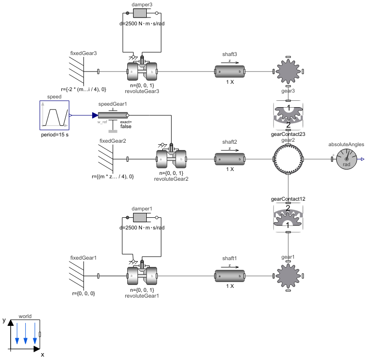
Diagram
Wolfram Language
In[1]:=
SystemModel["RotatingMachinery.Examples.Gears.SpurGears.InnerToOuterDrive"]
Out[1]:=
Information
Drive Inner Gear
This example shows how to combine an internal gear with inner and outer gearwheels in a model. The inner gearwheel (the ring) is driving the two outer gearwheels (the two wheels inside the ring).
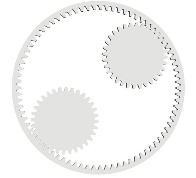
Figure 1: Inner driving two outer spur gears.
In this example, gear2 (inner) drives both outer gears. The contact forces are applied to outer gears by gearContact12 and gearContact23 components that are needed to assemble a gear mesh.
The module, number of teeth and clearence between the shafts are used in the calculation of the shaft positions (see GearTrain) for a satisfactory simulation.
Figure 2 shows the contact forces. Note how the line of contact changes during the simulation. Initially, there is a transient period before the contact stabilizes to a lower force level with two pairs of teeth in contact. Then, one pair of teeth goes out of contact, leaving only the current tooth to bear the force. After some time, a new pair of teeth will come into contact, causing the force level to drop once again.
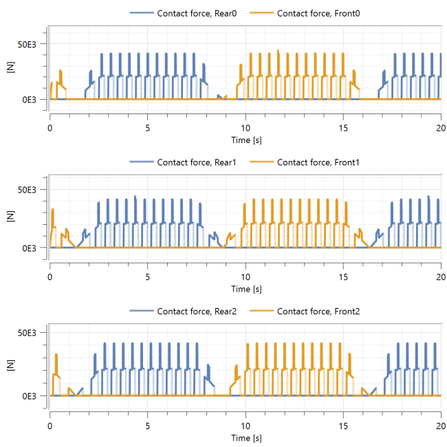
Figure 2: Teeth contact forces.
Parameters (10)
| m |
Value: 0.005 Type: Module (m) Description: Gear module |
|---|---|
| a12 |
Value: (m * z1 + m * z2) / 2 + m / 10 Type: Distance (m) Description: Distance from wheel center 1 to wheel center 2 |
| a23 |
Value: (m * z2 + m * z3) / 2 + m / 10 Type: Distance (m) Description: Distance from wheel center 2 to wheel center 3 |
| alpha0 |
Value: 20 * Modelica.Constants.pi / 180 Type: Angle (rad) Description: Reference profile angle |
| z1 |
Value: 32 Type: Integer Description: Number of teeth in wheel one |
| z2 |
Value: 80 Type: Integer Description: Number of teeth in wheel two |
| z3 |
Value: 32 Type: Integer Description: Number of teeth in wheel three |
| x1 |
Value: -0.2 Type: Real Description: Profile shift for gear wheel one |
| x2 |
Value: 0 Type: Real Description: Profile shift for gear wheel two |
| x3 |
Value: -0.3 Type: Real Description: Profile shift for gear wheel three |
Components (20)
| world |
Type: World Description: World coordinate system + gravity field + default animation definition |
|
|---|---|---|
| fixedGear1 |
Type: Fixed Description: Frame fixed in the world frame at a given position |
|
| revoluteGear1 |
Type: Revolute Description: Revolute joint (1 rotational degree-of-freedom, 2 potential states, optional axis flange) |
|
| speedGear1 |
Type: Speed Description: Forced movement of a flange according to a reference angular velocity signal |
|
| gear1 |
Type: SpurGear Description: Spur gear with mass, rotations and visualization |
|
| revoluteGear2 |
Type: Revolute Description: Revolute joint (1 rotational degree-of-freedom, 2 potential states, optional axis flange) |
|
| fixedGear2 |
Type: Fixed Description: Frame fixed in the world frame at a given position |
|
| gear2 |
Type: SpurGear Description: Spur gear with mass, rotations and visualization |
|
| absoluteAngles |
Type: AbsoluteAngles Description: Measure absolute angles between frame connector and the world frame |
|
| speed |
Type: Trapezoid Description: Generate trapezoidal signal of type Real |
|
| gear3 |
Type: SpurGear Description: Spur gear with mass, rotations and visualization |
|
| revoluteGear3 |
Type: Revolute Description: Revolute joint (1 rotational degree-of-freedom, 2 potential states, optional axis flange) |
|
| damper3 |
Type: Damper Description: Linear 1D rotational damper |
|
| fixedGear3 |
Type: Fixed Description: Frame fixed in the world frame at a given position |
|
| damper1 |
Type: Damper Description: Linear 1D rotational damper |
|
| gearContact12 |
Type: GearForceCalculationInner Description: Class calculating internal gear mesh contact forces |
|
| shaft2 |
Type: CylindricalBeam Description: Class with a flexible cylindrical beam |
|
| shaft1 |
Type: CylindricalBeam Description: Class with a flexible cylindrical beam |
|
| shaft3 |
Type: CylindricalBeam Description: Class with a flexible cylindrical beam |
|
| gearContact23 |
Type: GearForceCalculationInner Description: Class calculating internal gear mesh contact forces |