WOLFRAM SYSTEM MODELER
GettingStartedGetting Started |
|
Wolfram Language
In[1]:=
SystemModel["RotatingMachinery.GettingStarted"]
Out[1]:=
Information
The Rotating Machinery library enables the user to model and simulate rotating types of machinery. This guide introduces how to set up a model for simulating the behavior of the rotating machinery and how to utilize the library's features.
An introduction to the contents of the library is presented here. Basic knowledge of System Modeler is assumed for this guide. We recommend that you have a look at the learning resources if you are not familiar with System Modeler.
The library focuses on analyzing various types of rotating machinery behavior, such as excessive vibrations, unbalanced masses, critical speed, etc. The built-in ExternalDamping example, a Jeffcott rotor [1], will be used to introduce how to model, simulate and animate models.
Model description
The Jeffcott rotor, Figure 1, example (a generic turbine model) consists of a disk attached to a shaft supported by pinned supports. The right support is not restricted on the shaft's longitudinal axis to avoid applying additional forces to the shaft. A power source is then connected to the shaft and support. A flexible support underpins the turbine to reduce the vibrations.
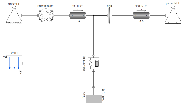
Figure 1: Jeffcott rotor.
The World component
Just like the MultiBody library, any simulation models in the Rotating Machinery library must include the World model declared as an inner component at the top level. The world object defines the gravity field and default animation shapes for the model.
General Settings
When components are connected to fixed supports, additional constraints are set. This can cause the equation systems to become overdetermined, meaning there are more equations than variables. This cannot be solved automatically without additional information. To fix this, the modeler can relax constraints by modifying the parameters enforceState_a, and enforceState_b in shafts and isRoot in flexible supports.
The number of constraints that need to be relaxed is equal to the number of components connected to a fixed support minus one. In this example, there are three such components, powerSource, shaftNDE, and extDamping (connected to pinnedDE, pinnedNDE and ground, respectively).
A strategy for selecting parameters is to divide and conquer.
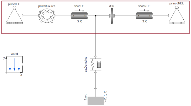
Figure 2: The first part to focus on.
Start by focusing on the part of the model that is between the two pinned supports, marked with a red border in Figure 2. This part of the system has two fixed supports, pinnedDE and pinnedNDE, meaning that one extra constraint needs to be relaxed. The parameter enforceStates_b is set to true by default, and the system can be relaxed by setting it to false. In this case, it can be changed either in shaftDE or shaftNDE. In the example, enforceStates_b has been set to false.
Note that in more advanced cases, such as systems connected in loops, there are cases where enforceStates_a needs to be changed to true, but in the general case, there is no need to change this value.

Figure 3: Flexible support.
Next, look at the part connecting the system to the ground. There are now three fixed supports which means that apart from the shaftNDE, one more constraint needs to be relaxed. Thus, extDamping, a flexible support, constraint is relaxed by setting isRoot option to true.
More information regarding prioritized constraints (roots) are found in the Modelica specification.
Supports
All models will need one or more supports. In this model, the pinned supports named pinnedDE and pinnedNDE are connected to a beam on the drive and non-drive sides, respectively. These can function as either a hinged or roller support, depending on the value of the parameter axialField. In this case, it is set to false, meaning it will act as a rolling support in which the axial position is not fixed.
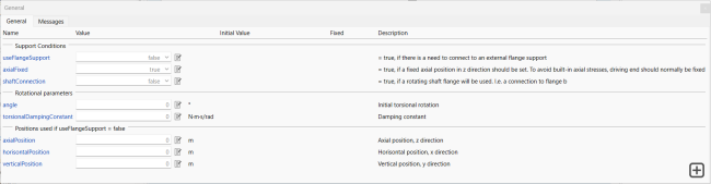
Figure 4: Support parameters tab.
There are two other types of supports: fixed (from the Multibody library) and flexible supports. A fixed support completely restricts movement in all directions, whereas a flexible support allows the connected member to move according to its structural constants such as stiffness and damping parameters. The flexible support parameters are given in Figure 5.

Figure 5: Flexible support parameters tab.
Under the Settings section, it is recommended to set isRoot to false as long as there are any other types of support. For more details on isRoot, see the General Settings section.
Shafts
The shafts in the library are flexible, meaning they deflect under applied loads and have a high level of accuracy.
Users should define dimensions and material properties of the shaft. Increasing the number of elements (n) will improve the accuracy and fidelity of the model, with higher computational cost.
When a shaft is connected to multiple supports, the system becomes overdetermined, and the solution depends on the chosen constraints. In this case, the system has two fixed supports, pinnedDE and pinnedNDE, meaning that one extra constraint needs to be relaxed. The parameter enforceStates_b is set to true by default and the system can be relaxed by setting it to false. In this example, eforceStates_b has been set to false. As a rule of thumb, enforceStates_a is false for all elements and enforceStates_b is true for all elements until it is connected to a constrained support, i.e. normally the last element.
To accurately calculate the orientation of each segmented piece of a beam as it deflects, it is necessary to evaluate the orientation. However, when working with a generic flexible beam, constraints can affect the calculation of the orientation. The resolveInFrame parameter allows users to choose how the orientation is calculated. The default value for this parameter is typically sufficient.

Figure 6: Shaft parameters tab.
Power Source
The powerSource provides the torque needed to run the machinery, with a PID controller option that helps to regulate the rotational speed. The powerSource is initiated by the shaft if the speed is not regulated. It is also possible to use components from the Multibody.Forces library as power sources.
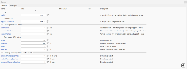
Figure 7: Power source parameters tab.
To connect the

powerSource to a support system, the parameter supportConnection should be set to true, otherwise it will be assumed to be grounded.
Disk
In this model, each disk represents a blade or paddle on the rotor shaft.
Figure 8: Power source parameters tab.
To model the unbalanced mass of the disks in the simulation, you can use the imbalance parameters to predict their effects on the behavior of the turbine.
Improving model fidelity
As shown in Figure 9, it is possible to used detailed bearing models instead of the standard supports. In this case, NSK bearings have been used.
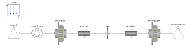 Figure 9: Turbine with bearings.
To customize these NSK bearings, values can be set on the Bearing Dimensions tab. This tab allows for the customization of almost any cylindrical roller bearing. Additionally, on the General tab, it is possible to apply defects to the outer ring using a force. This allows for the monitoring of vibrations caused by bearing defects.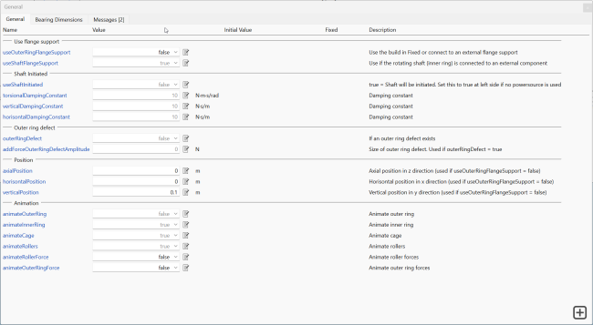
Figure 10: Bearing parameter tab.
In addition, these bearings have flanges on the outer ring for connection and they can be placed on top of the supports. By enabling outerRingFlangeSupport, the bearing can be connected to a flexible support, as illustrated in Figure 11.
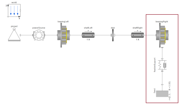
Figure 11: Steam turbine with one bearing on a flexible support.
Simulation
Once the design parameters have been set, the Jeffcott rotor model is ready to be used. It is now possible to use it for By simulating the turbine, we can gain a better understanding of its performance and improve its design, leading to more efficient and effective machinery.
Solver settings
Note that the bearings trigger many events due to contact, thus simulation tolerance settings are important to find the right balance between simulation speed and precison. In this example the following settings have been chosen:
- Solver = CVODEs
- Tolerance = 1e-5
- Event Hysteresis Epsilon = 1e-8
References
[1] Jeffcott, H. H. "XXVII. The Lateral Vibration of Loaded Shafts in the Neighbourhood of a Whirling Speed. The Effect of Want of Balance." The London, Edinburgh, and Dublin Philosophical Magazine and Journal of Science 37, no. 219 (1919): 304-314. https://doi.org/10.1080/14786440308635889.